Pleiger Elektronik
GmbH & Co. KG
Page: 32 Manual for 362MC Edition: 6/2007 Subject to modifications
All analogue inputs are electrically interconnected and connected to protective earth.
""
""
"
362MC
T
362MC
T
362MC
T
R
L
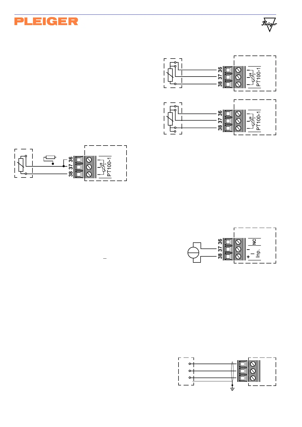
9.8 Connection of the PT100 sensor
In the standard configuration of the 362MC, the
1
st
and 2
nd
analogue inputs serve as PT100 inputs.
Connection is effected via a three-wire connection,
whereby the compensation for the line resistance
of 3 wires is based on 3 wires of the same cross-
section and the same length.
As the examples opposite show, it is also possible
to connect a 4-wire PT100 sensor in 3-wire
configuration without any problems whatsoever.
If a 4-wire system is already installed, such as is
employed on the 362-D for example, the 4
th
wire
is not to be connected.
When using a 2-wire PT100 sensor, e.g. for trend
compensation, connection is to be carried out as
shown in the example opposite.
The line resistance is not compensated in this
case; the absolute measured value is
consequently corrupted in many installations.
Installation via a 2-wire connection is sufficient for use as a differential trend input. Should you desire a
more accurate indication or wish to use the sensor as a main sensor, however, external compensation is
possible with a resistor between terminal 36 and 37. The resistance value for R
L
must correspond to the
resistance of one connecting wire.
9.9 Connection of a I -value transmitter at the 1
st
analogue input
In the special configuration of the 362MC, the
1
st
analogue input serves as a linear current input
for currents from 4-20mA. The current input is
configured as a differential amplifier input.
The max. common-mode voltage is +2V.
If potential-free current sources, like P/I-converters,
are used the inverted input should be connected to 0V
in order to improve the noise immunity (link between terminal 36 and 37).
9.10 Connecting cable
Shielded, twisted-pair cabling is to be used for the analogue outputs (see Hardware extension), the
communication interface (see Hardware extension) and analogue inputs 3 and 4 which are described here
(resistance and U/I). The cable cross-section must be at least 0.22mm².
Shielded cabling with a minimum cable cross-section of 0.5mm² is to be used for the binary inputs and
analogue inputs 1 and 2 (PT100).
It is recommended that shielded cabling be used for the switching outputs.
The shields of all connection cables are to be
connected to control cabinet earth, ensuring a
substantial contact surface area. The cabling
should be as short as possible and have an
adequate cross-section.
""
""
"
362MC
362MC
1
st
analogue input
as current input
I= 4-20mA