Pleiger Elektronik
GmbH & Co. KG
Edition: 6/2007 Subject to modifications Manual for 362MC Page: 23
In order to use the 2
nd
relay set (2Relay) or the analogue outputs (1Lin... and 1Lin...),
hardware extensions are required.
""
""
"
OutputYOutputY
OutputYOutputY
OutputY
1Relay 1Relay
1Relay 1Relay
1Relay 362MC output assignment for 362-D function
OutputXOutputX
OutputXOutputX
OutputX
NC NC
NC NC
NC
OutputYOutputY
OutputYOutputY
OutputY
1Lin 0>1Lin 0>
1Lin 0>1Lin 0>
1Lin 0> 362MC output assignment for 361-D function
OutputXOutputX
OutputXOutputX
OutputX
NC NC
NC NC
NC
""
""
"
In standard configuration, the PT100 inputs of the 362MC are calibrated for 0-200°C.
In this case the scaling is always Scale-0 = 0, Scale-F = 200, Dim = °C.
""
""
"
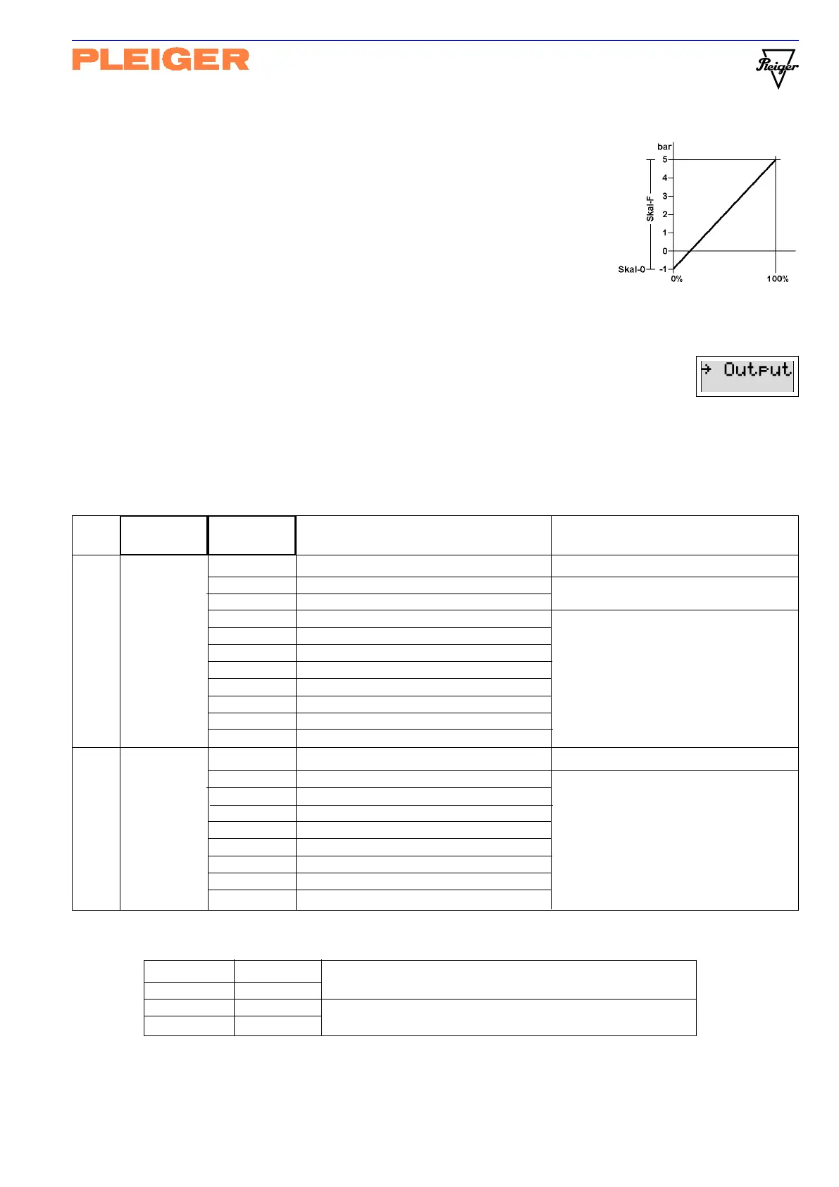
Example
If a pressure transmitter with a physical measuring range from -1 bar to
+5 bar in accordance with the characteristic shown opposite is connected
at the input of the 362MC, scaling will be effected
in bar as follows: Scale-0 = -1 Scale-F = 6 Dim = B
in % as follows: Scale-0 = 0 Scale-F = 100 Dim = %
See also
Explanatory note on setpoints (5.3.1)
5.7 Output menu
In the output menu, the internal output variables of the 362MC are assigned to the
physical outputs. This assignment is to be defined separately for each profile and thus
for each ofthe two controllers of the 362MC. Double assignments are not expedient and are thus not
permissible for entry. The following table shows the assignments for controller output and actual-value
output. The hardware configuration of the 362MC is to be observed in each case!
Attention: Avoid double assignment in case of changing the controller profile!
The following example contains the assignment of the 362MC´s physical outputs which would correspond to the
functions of a 361-D or 362-D:
in the Parameter Value (min Meaning Comment
profile each controller max)
OutputY OutputY
OutputY OutputY
OutputY
NC NC
NC NC
NC No output assigned
1Relay 1Relay
1Relay 1Relay
1Relay 1
st
relay set (Rel+ and Rel-) 2
nd
relay set only when
2Relay 2Relay
2Relay 2Relay
2Relay 2
nd
relay set (Rel+ and Rel-) hardware extension installed
1Lin 0>1Lin 0>
1Lin 0>1Lin 0>
1Lin 0> 1
st
analogue output 0-20mA (0-5/10V) 1
st
and 2
nd
analogue (linear) output
1Lin 4>1Lin 4>
1Lin 4>1Lin 4>
1Lin 4> 1
st
analogue output 4-20mA only with hardware extension
1Lin 0<1Lin 0<
1Lin 0<1Lin 0<
1Lin 0< 1
st
analogue output 20-0mA (5/10-0V) > standard direction (Ymin=0%)
1Lin 4<1Lin 4<
1Lin 4<1Lin 4<
1Lin 4< 1
st
analogue output 20-4mA 0-20mA, 4-20mA, 0-10V, 0-5V
2Lin 0>2Lin 0>
2Lin 0>2Lin 0>
2Lin 0> 2
nd
analogue output 0-20mA (0-5/10V) < reversed direction (Ymin=0%)
2Lin 4>2Lin 4>
2Lin 4>2Lin 4>
2Lin 4> 2
nd
analogue output 4-20mA 20-0mA, 20-4mA, 10-0V, 5-0V
2Lin 0<2Lin 0<
2Lin 0<2Lin 0<
2Lin 0< 2
nd
analogue output 20-0mA (5/10-0V) Bidirectional output with 0>
2Lin 4<2Lin 4<
2Lin 4<2Lin 4<
2Lin 4< 2
nd
analogue output 20-4mA (Ymin=-100%), ±20mA, ±10V, ±5V
OutputXOutputX
OutputXOutputX
OutputX
NC NC
NC NC
NC No output assigned
1Lin 0>1Lin 0>
1Lin 0>1Lin 0>
1Lin 0> 1
st
analogue output 0-20mA (0-5/10V) 1
st
and 2
nd
analogue (linear) output
1Lin 4>1Lin 4>
1Lin 4>1Lin 4>
1Lin 4> 1
st
analogue output 4-20mA only with hardware extension
1Lin 0<1Lin 0<
1Lin 0<1Lin 0<
1Lin 0< 1
st
analogue output 20-0mA (5/10-0V) > standard direction (Ymin=0%)
1Lin 4<1Lin 4<
1Lin 4<1Lin 4<
1Lin 4< 1
st
analogue output 20-4mA 0-20mA, 4-20mA, 0-10V, 0-5V
2Lin 0>2Lin 0>
2Lin 0>2Lin 0>
2Lin 0> 2
nd
analogue output 0-20mA (0-5/10V) < reversed direction (Ymin=0%)
2Lin 4>2Lin 4>
2Lin 4>2Lin 4>
2Lin 4> 2
nd
analogue output 4-20mA 20-0mA, 20-4mA, 10-0V, 5-0V
2Lin 0<2Lin 0<
2Lin 0<2Lin 0<
2Lin 0< 2
nd
analogue output 20-0mA (5/10-0V) Bidirectional output with 0>
2Lin 4<2Lin 4<
2Lin 4<2Lin 4<
2Lin 4< 2
nd
analogue output 20-4mA (Ymin=-100%), ±20mA, ±10V, ±5V