Pleiger Elektronik
GmbH & Co. KG
Page: 26 Manual for 362MC Edition: 6/2007 Subject to modifications
6.1.3 Explanatory note on the Reset function for the controller
Param, ROM and RAM errors can only be acknowledged by resetting the controller, after which the
system monitoring process is repeated.
6.1.4 Explanatory note on Watchdog error
The 362MC incorporates a programme run monitoring function. The correctly running controller
programme regularly resets a watchdog timer. Should deviations occur during execution of the
programme, e.g. as a result of major external EMC disturbances, this resetting pulse will not be
transmitted for the timer. The watchdog timer will then initiate a programme restart. During the restart,
the cause Watchdog error is displayed. The controller programme is not stopped. This error is to be
acknowledged by pressing the Exit button, in the same manner as other error messages.
6.2 Sensor monitoring functions
The 362MC continuously checks the measured-value inputs for interruptions, short-circuits or other
deviations from the measuring range in the background during normal running of the controller
programme. As a general principle, only those errors are monitored which could actually disturb
operations on the basis of the currently parameterised functions.
Unused inputs and inputs only employed for display purpose are not monitored.
The following table provides an overview of the various error messages.
Error
display
ERRORERROR
ERRORERROR
ERROR
1.PT >11.PT >1
1.PT >11.PT >1
1.PT >1
1 >20mA1 >20mA
1 >20mA1 >20mA
1 >20mA
ERRORERROR
ERRORERROR
ERROR
1.PT <01.PT <0
1.PT <01.PT <0
1.PT <0
1 < 4mA1 < 4mA
1 < 4mA1 < 4mA
1 < 4mA
ERRORERROR
ERRORERROR
ERROR
2.PT >12.PT >1
2.PT >12.PT >1
2.PT >1
ERRORERROR
ERRORERROR
ERROR
2.PT <02.PT <0
2.PT <02.PT <0
2.PT <0
ERRORERROR
ERRORERROR
ERROR
Lin >1Lin >1
Lin >1Lin >1
Lin >1
ERRORERROR
ERRORERROR
ERROR
Lin <0Lin <0
Lin <0Lin <0
Lin <0
ERRORERROR
ERRORERROR
ERROR
Resist>1Resist>1
Resist>1Resist>1
Resist>1
ERRORERROR
ERRORERROR
ERROR
Resist<0Resist<0
Resist<0Resist<0
Resist<0
Monitoring function
for analogue inputs
The 1
st
PT100 input has a measured value
> measuring range (standard > 200°C, opt. > 500°C)
or > 20mA (optional > 100%).
The 1
st
PT100 input has a measured value
< measuring range (standard < 0°C)
or < 4mA (optional < 0%).
The 2
nd
PT100 input has a measured value
> measuring range (standard > 200°C).
The 2
nd
PT100 input has a measured value
< measuring range (standard < 0°C).
The 3
rd
analogue input has a measured value
> measuring range (standard > 20mA, opt. > 5V/10V).
The 3
rd
analogue input has a measured value
< measuring range (standard < 0(4)mA, opt. > 0V).
The resistance input has a measured value
> calibrated range (> Rmax).
The resistance input has a measured value
< calibrated range (< Rmin).
Additional measures
If the input to which the error message
relates is in use as
an actual-value input,
a setpoint input,
a trend input or
a disturbance input,
the controller programme will be stopped and
an alarm will be triggered.
The sensor and the connection cabling are to
be checked; an wire breakage, short-circuiting
or sensor defects are the most common causes
of these errors.
Beyond this, the measuring input of the
controller may be defective.This is to be checked
with a PT100 simulator or current source, for
example.
After error acknowledge, the test is repeated.
""
""
"
Errors at important inputs will lead to the controller programme being stopped and
initiation of an alarm, as safe and reliable operation of the controlled system is not
longer ensured. Please do not acknowledge the error message until the cause of
the error has been eradicated.
""
""
"
An error which does not recur immediately after being acknowledged indicates
a major EMC disturbance. Make a note of such errors. Should the error recur
frequently, the cause of the error is to be eradicated.
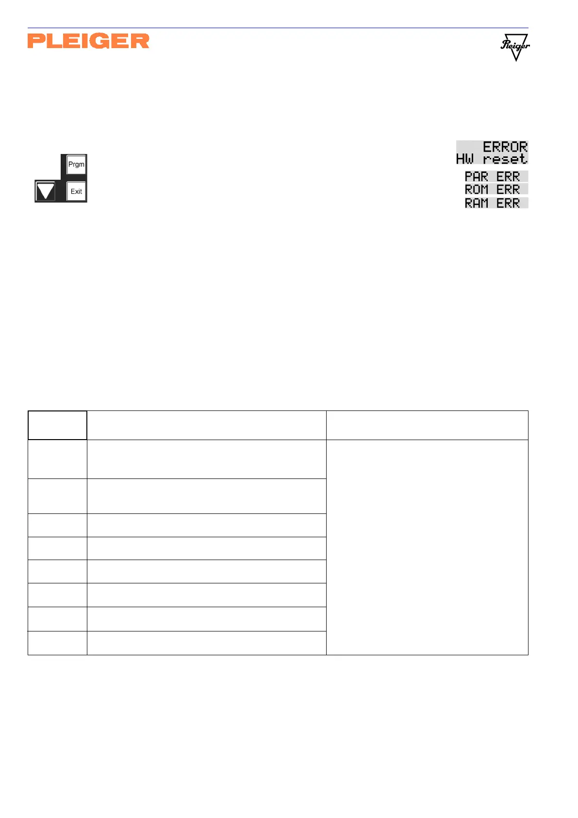
Controller reset These buttons are to be pressed simultaneously. The hardware reset
will be displayed. This display is to be acknowledged by pressing the
Exit button. At Programme start after reset these error messages
show any multiple errors corresponding to the errors which were
displayed briefly during the system monitoring process.