Pleiger Elektronik
GmbH & Co. KG
Edition: 6/2007 Subject to modifications Manual for 362MC Page: 29
9 Connection
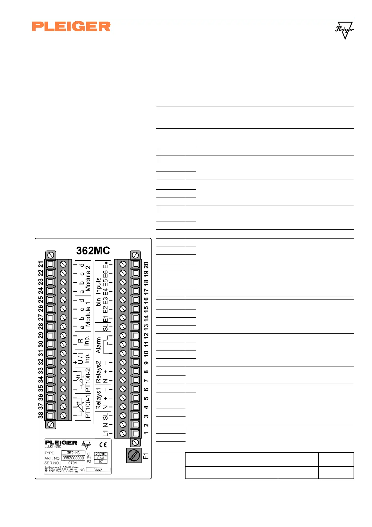
The connection points on the 362MC are grouped together on two screw-/plug terminals on the backside
of the controller. The voltage supply, the switching outputs, the alarm and the binary inputs are
connected via a 20-pole plug terminal; the analogue inputs and the signals from supplementary modules
are connected via an 18-pole plug terminal.
9.1 Terminal assignments
The terminals are numbered from
no. 1 to no. 38 and identified by
symbols printed on the backside
of the controller.
The connection table below is
followed by several explanatory
notes on the controller connections.
Additional explanatory notes on the
connection of hardware extensions
are to be found under
Hardware extension (Appendix)
Fuse F1 230 V-AC 115 V-AC
Value at voltage supply 0,1 AT 0,2 AT
Connection table (362MC standard configuration)
Terminal Signal name
1 L1 Voltage supply connection
2 N Standard 230V-AC (or 115V-AC)
3 SL Protective earth conductor or cabinet earth
4 N Output, 1
st
relay set
5 + (Open) Connection for 1
st
switching output
6 - (Closed)
7 N Output, 2
nd
relay set
8 + Connection for 2
nd
switching output
9 -(See Hardware extension in appendix B1)
10 Common
11 Make contact Alarm relay
12 Break contact
13 SL Protective earth conductor or cabinet earth
14 E1
15 E2
16 E3 Binary inputs
17 E4 for function switching
18 E5
19 E6
20 E (Common)
21 d
22 c Connection for extension module 2
23 b(
See hardware extension in appendix B2)
24 a
25 d
26 c Connection for extension module 1
27 b(See hardware extension in appendix B3)
28 a
29 Analogue input 4 (resistance)
30 Connection for resistor feedback sensor
31 - U/I Analogue input 3 (current/voltage)
32 + Connection for measured-value transmitter
33 Analogue input 2 (PT100)
34 (PT100-2) Connection for 2
nd
temperature sensor
35
36 Analogue input 1 (PT100)
37 (PT100-1) Connection for 1
st
temperature sensor
38 (In special version for 4-20mA)