Pleiger Elektronik
GmbH & Co. KG
Page: 42 Manual for 362MC Edition: 6/2007 Subject to modifications
D2-Anteil bei Tendenzaufschaltung
Parameterisation
As in the case of the standard controller, the D component for the controller with activated trend
compensation is also set via the control parameters Tv and Vd.
See also Controller parameters menu (5.5)
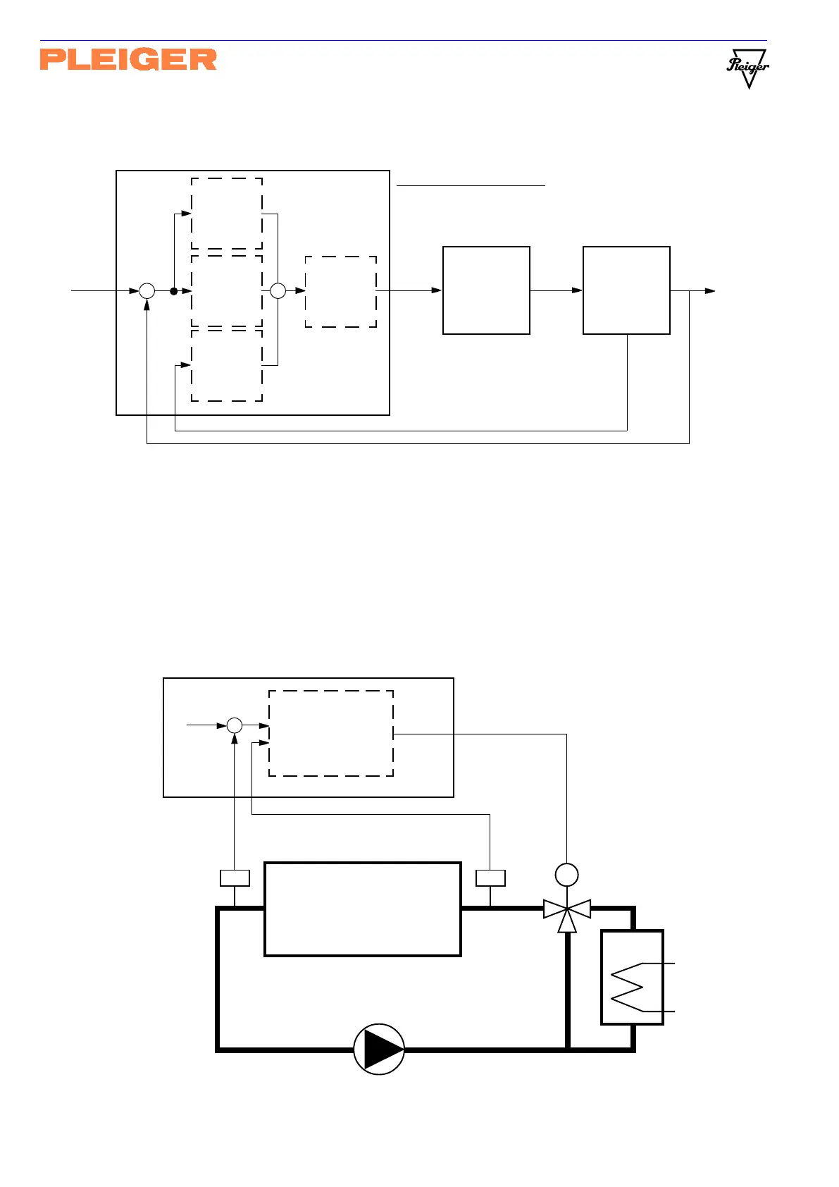
Example
The circuit diagram below shows a typical example of the use of the special trend compensation
function. Here, an inlet temperature sensor (T
IN
) has been added to the outlet temperature control (T
OUT
)
of a main engine. The effects of the dead time between the outlet temperature sensor and the mixing
valve are reduced substantially by means of the special trend compensation function
(parameter Trend = PT100-2).
Cooler
Main engine
M
T
OUT
PT100
Tend D
3-Point
step controller
T
IN
PT100
PT100-1 PT100-2
TTTT
ActV X
Out+Y
1Relay
362MC
Setp W
-
362MC with trend compensation
(Structure with D2) in input menu:
ActValX = PT100-1
Tend = PT100-2
Tend D
ActV X
Switching
output
or
Analogue
output
Setp W dx
-
Out+Y
Out%Y
I-
controller
P-
controller
Actuator Controlled
system
Feed Y
D2-
controller