CLUTCHING
6.21
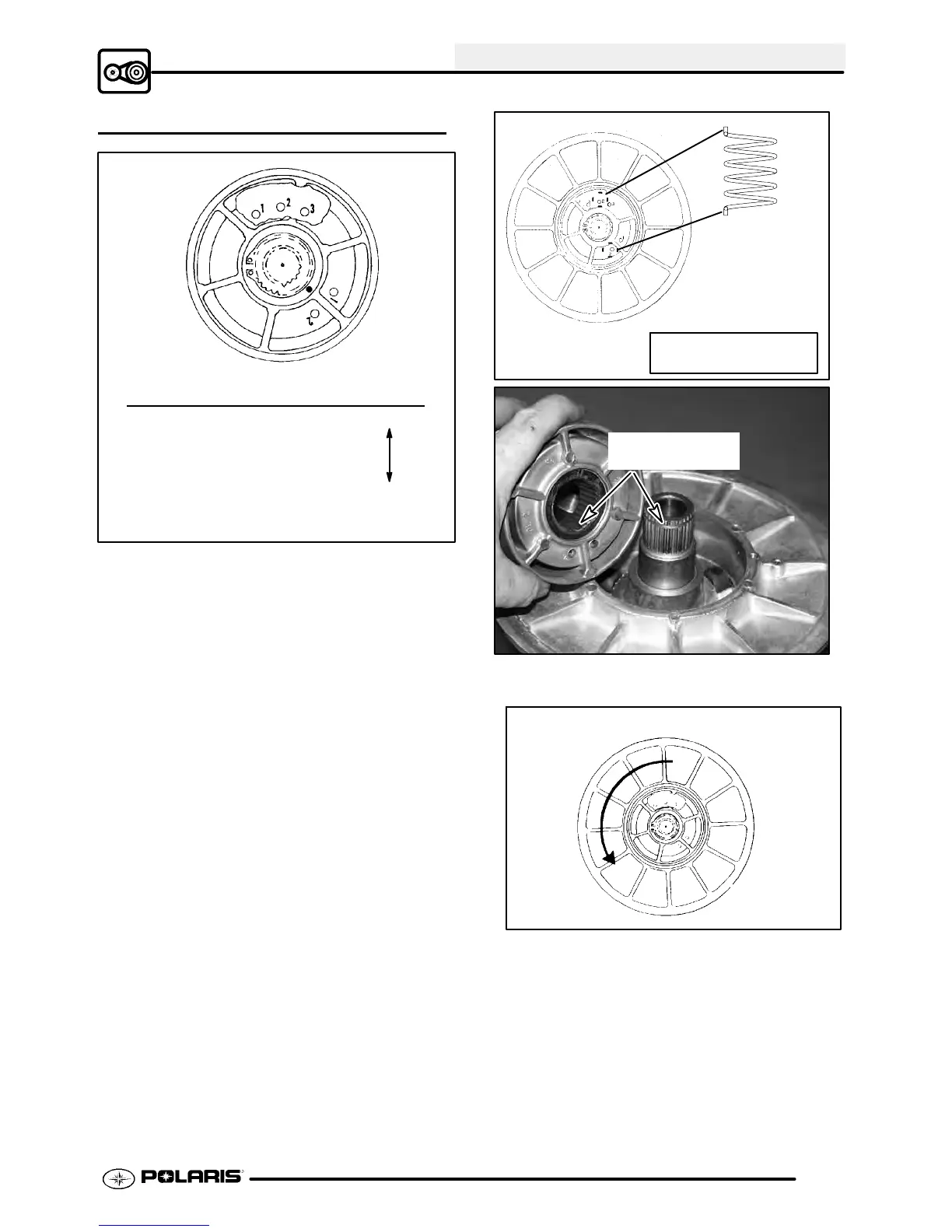
DRIVEN CLUTCH ASSEMBLY
Moveable Spring
Example: Helix Sheave Tension
2 -- 1 Heavy
Spring/ 2 -- 2
Position 1 -- 1
2--3
1--2
1--3 Soft
Refer to General Information Chapter 1 for driv-
en clutch spring color and production setting.
1. Install moveable sheave with spacer washers.
Important: At least one spacer washer must be
installed. Teflont bushings are self-lubricating.
Do not apply oil or grease to the bushings.
2. Install spring, inserting spring tabintoproperhole
in moveable sheave.
3. Insert spring tab into proper hole in helix. See
specifications in Chapter 1 or in Illustration 2
above.
The driven clutch, helix/moveable assembly has
several different spring locations which affect clutch
shifting and RPMs. The greatest amount of spring
tension will raise engine RPMs during clutch upshift
and allow quicker backshift or downshift when pulling
or negotiatinga hill, for example. Theleast amount of
tension will create a slower downshift and a harder
upshift.
Driven Clutch
Driven Spring
Scrambler 500 Driven
Spring Placement: 1--1
Ill. 2
Align boss spline
to install helix
4. Line up boss spline and push helix down until it
engages the splines 1/2″ to 3/4″.
1/3
turn
5. While holding downward pressure on helix, wind
moveable sheave counterclockwise
approximately 1/3 turn (120°).
6. Push helix into place and install snap ring.

 Loading...