CLUTCHING
6.13
c) “X”, or the marks that were made earlier,
under weight
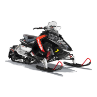
Spacer washers
2. Install moveable sheave onto fixed sheave.
3. Install spider spacers. Use same quantity and
thickness as were removed.
4. Compress spider buttons for each tower and
install spider, making sure that “X”, or the marks
that were made earlier, on spider aligns with “X”,
or the marks that were made earlier, in moveable
sheave.
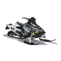
5. Torque spider to specification using the holding
fixture and spider tool. Torque with smooth
motionto avoid damageto thestationary sheave.
Refer to Page 6.2 for torque specification.
CAUTION:
Be sure the spider spacer washers are fully seatedin
therecessedareainthespider. Anymisalignmentwill
alter clutch balance. Inverting the clutch while initially
tightening the spider will help position the washers.
Rotation
Nut on trailing side
6. Install shift weights using new lock nuts on the
bolts.
7. Reinstall clutch spring.
Spider Torque:
200 ft. lbs. (276 Nm)
Cover Screw Torque:
90 in. lbs. (10.4 Nm)
8. Reinstall cover, aligning bosses on the tower and
cover. Torque coverboltsevenlytospecification.
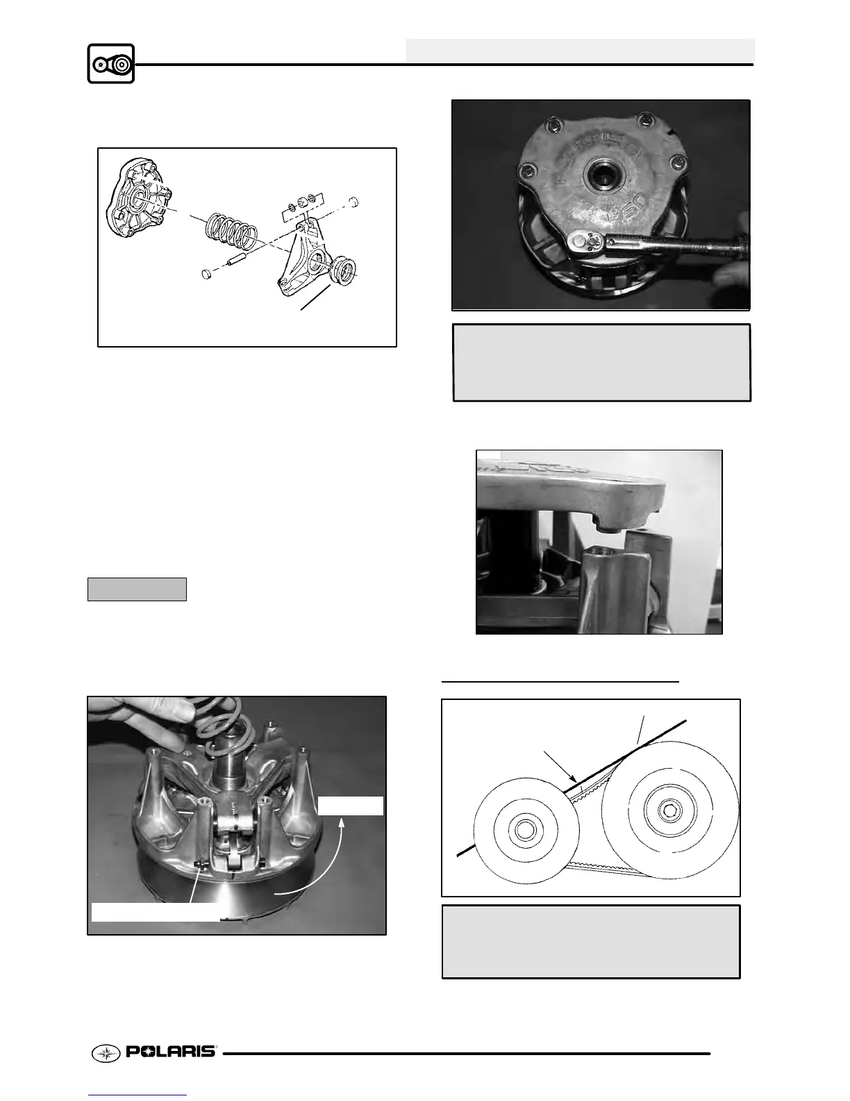
DRIVE BELT TENSION
11/8″ (28.5 mm)
Straight Edge
Belt Deflection (Tension):
11/8″ (2.9 cm) - 1 1/4″ (3.2 cm)

 Loading...