ENGINE
3.42
4. Install the crankcase flange bolts and tighten in 3
steps following the pattern on Page 3.2 to
specified torque.
Crankcase Bolt Torque:
14 ft. lbs. (19 Nm)
Crankcase Sealant:
(PN 2871557)
WATER PUMP MECHANICAL
SEAL INSTALLATION
1. Clean the seal cavity to remove all traces of old
sealer .
2. Place a new mechanical seal in the seal drive
collar , and install on the pump shaft.
3. Screw the guide onto the end of the pump shaft.
4. Installthewasherandnutandtightentodrawseal
into place until fully seated.
5. Remove the guide adaptor using the additional
nut as a jam nut if necessary.
WATER PUMP MECHANICAL
SEAL REMOVAL -
ENGINE
INSTALLED
W ater Pump Mechanical Seal
Puller: (PN 2872105)
Replacement T--Handle:
(PN 2872106)
This tool allows a technician to replace the
mechanical water pump seal on EH50PL engines
without removing the engine and splitting the cases.
CAUTION:
Improperor carelessuseof thistoolorprocedurecan
result in a bent water pump shaft. Pump shaft
replacement requires engine removal and crankcase
separation. Use caution while performing this
procedure. Make surethat the puller is parallel tothe
shaft at alltimes. Donot placesideloadsonthewater
pump shaft or strike the puller or shaft in any way.
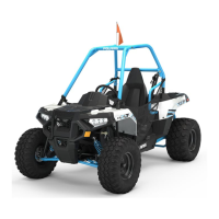
Ill. 1
Impeller
Sealing Washer
Coolant Drain
Bolt
Mechanical Seal
Oil
Seal
Sealing Washer
(Copper or Aluminum)
1. After the coolant has been drained, remove the
water pump cover, impeller and the sealing
washer . (Ill. 1)
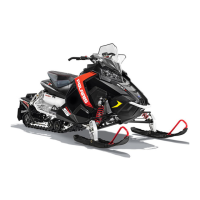
Ill. 2
T -Handle
Main Puller Body
2. Slide the main puller body over the outer portion
of the mechanical seal as shown in Ill. 2 and turn
T -Handle clockwise until it contacts water pump
shaft. Continue rotating until outer portion of
mechanical seal is separated from the metalseal
body.
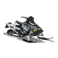
3. Insert the puller legs between the water pump
drive shaft and the remaining portion of the
mechanical seal. Attach the puller legs to the
main puller body. Ill. 3
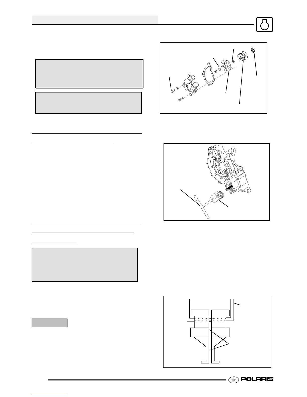
Ill. 4
Position the split
90° to opening
on main puller
body
Main puller
body

 Loading...