ENGINE
3.43
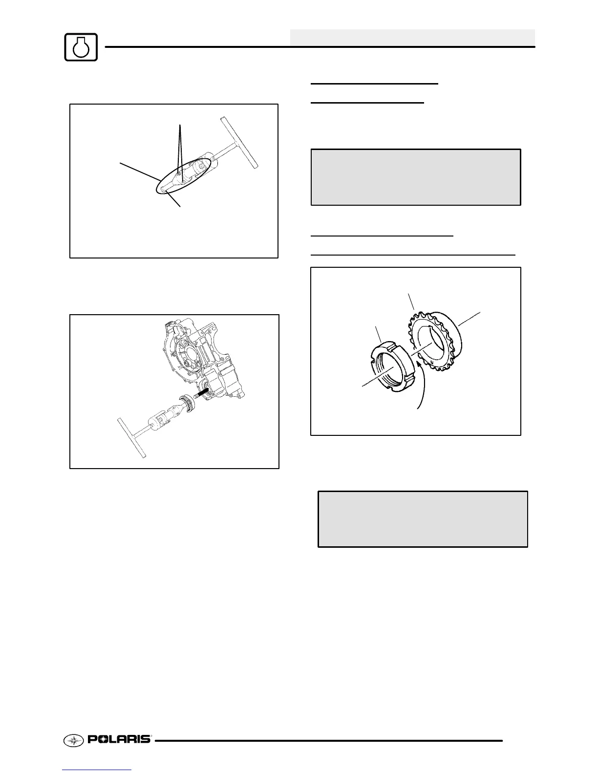
4. Ensure that the split between the puller legs is
fully supported by the main body of thetool (Ill 4).
Hex Socket Screws
Ill. 5
Lip must grasp inside
of mechanical seal.
Puller Legs
5. Tighten the hex socket screws on the puller legs
sufficiently so the lip of the puller legs will grasp
the mechanical seal. Ill. 5
Ill. 6
6. Turn the puller T-Handle clockwise until it
contacts the waterpumpshaft. Continuerotating
untiltheremainingportionof mechanical sealhas
been removed from the cases. Ill. 6 Pump shaft
oil seal can also be replaced at this time if
necessary.
7. The Water Pump Install Kit (PN 5131 135)is
required to install the new mechanical seal. This
tool is available separately and it is also included
in the Crankshaft/Water Pump Seal Installation
Kit (PN 2871283).
ONE WAY VALVE
INSTALLA
TION
Install the one way valve plunger, spring, and plug
using a new sealing washer.
One Way Valve Plug Torque:
16 ft. lbs. (22 Nm)
CAM CHAIN DRIVE
SPROCKET INSTALLA
TION
A
B
T ighten
1. Install the Woodruff key, drive sprocket, and
slotted nut. T ighten the nut to the specified
torque.
Slotted Nut Torque:
35-51 ft. lbs. (47-69 Nm)

 Loading...