BODY / STEERING / SUSPENSION
5.4
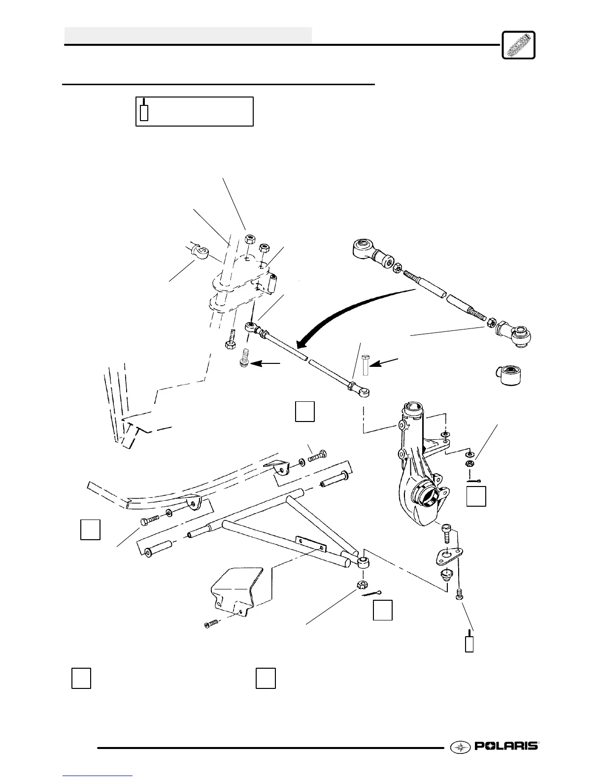
STEERING ASSEMBLY, EXPLODED VIEW
25-30 ft. lbs.
(35-41 Nm)
8 ft. lbs.
(11 Nm)
25 ft. lbs.
(35 Nm)
30 ft. lbs.
41 Nm)
Always use new bolts
upon reassembly
Always use new cotter pins upon
reassembly. Install w/ open end to-
ward rear of machine.
B
1
2
1
30 ft. lbs.
41 Nm)
A
2
12-14 ft. lbs.
(17-17 Nm)
40-45 ft. lbs.
54-61 Nm)
Steering Post
Steering Post
Arm (Frog)
Left Hand T ie
Rod End
Positioned
Below Steer-
ing Post Arms
1
2
Right Hand Tie
Rod End Positioned
Between Steering
Post Arms
NOTE:
To avoid damage to tie rods and other steering
components, be sure to install tie rod end bolts in the
proper direction. The steering post arm bolt (B) points up;
the rod end bolts (A) point down. Be sure inner rod ends
are positioned properly. The right inner rod end must be
placed between the steering post arms. The left inner rod
end must be below the lower arm as shown.
Apply Loctitet 242 to
the bolt threads.
242
242

 Loading...