Title Guidance
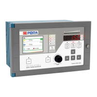
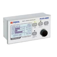
1 LCD Screen It shows current status, values of data setting and output.
2
LED for indicating
status
HEALTH It becomes on when power status of a product is good.
ALARM It is on when alarm occurs.
ZERO It is on when zero tension value is 0.
REMOTE It is on when input contact point from external digital is being used.
3 Fn button
Input briefly It switches screen mode.
Input longer It vitalizes external digital (remote) input.
4
LED for indicating
tension
It shows current tension values based on an area before tension.
5
FND for indicating
tension
It shows tension values as kg or N (Selectable).
6 Automatic Button
It switches operation mode into automatic mode.
It operates as ESC button in setting mode, it is able to return to previous item or cancel.
7 Manual button It can switch operation mode to manual mode.
8 Output button
It sets status of output to On/Off.
It operates as [input button] in setting mode and it can choose an item and save setting values.
9
Up/Down/Left/
Right button
Up/Down button
In automatic mode, it adjusts values when setting P·I·D sensitivity.
It adjusts the range indicating tension at tendency graph display.
Left/Right Button
It adjusts Time/Div at tendency graph screen.
In automatic mode, it shifts an item when setting P·I·D sensitivity.
In setting mode, it shifts a screen, an item and a cipher of setting values.
10 Dial button
Input briefly
In every kind of mode, it operates as [ENTER button].
Auto/Manual mode: It shifts a setting item
(Target tension, Manual output).
Input longer
Manual mode: It enters to setting mode.
Automatic mode: It enters to the mode of P·I·D sensitivity adjustment.
(When it is possible to P·I·D setting.
11 Zero button Input longer It adjusts current tension values to be zero.
12 Preset button Input longer Control shaft (A/B) is switched.
※ The limited function only for
PR-DTC-4100.AD
13
Indicating the
status of control
shaft
It indicates current status of control shaft as LED.
14 Lock button Input longer It vitalizes button lock function.
15 Serial port It is used for product firmware upgrade.
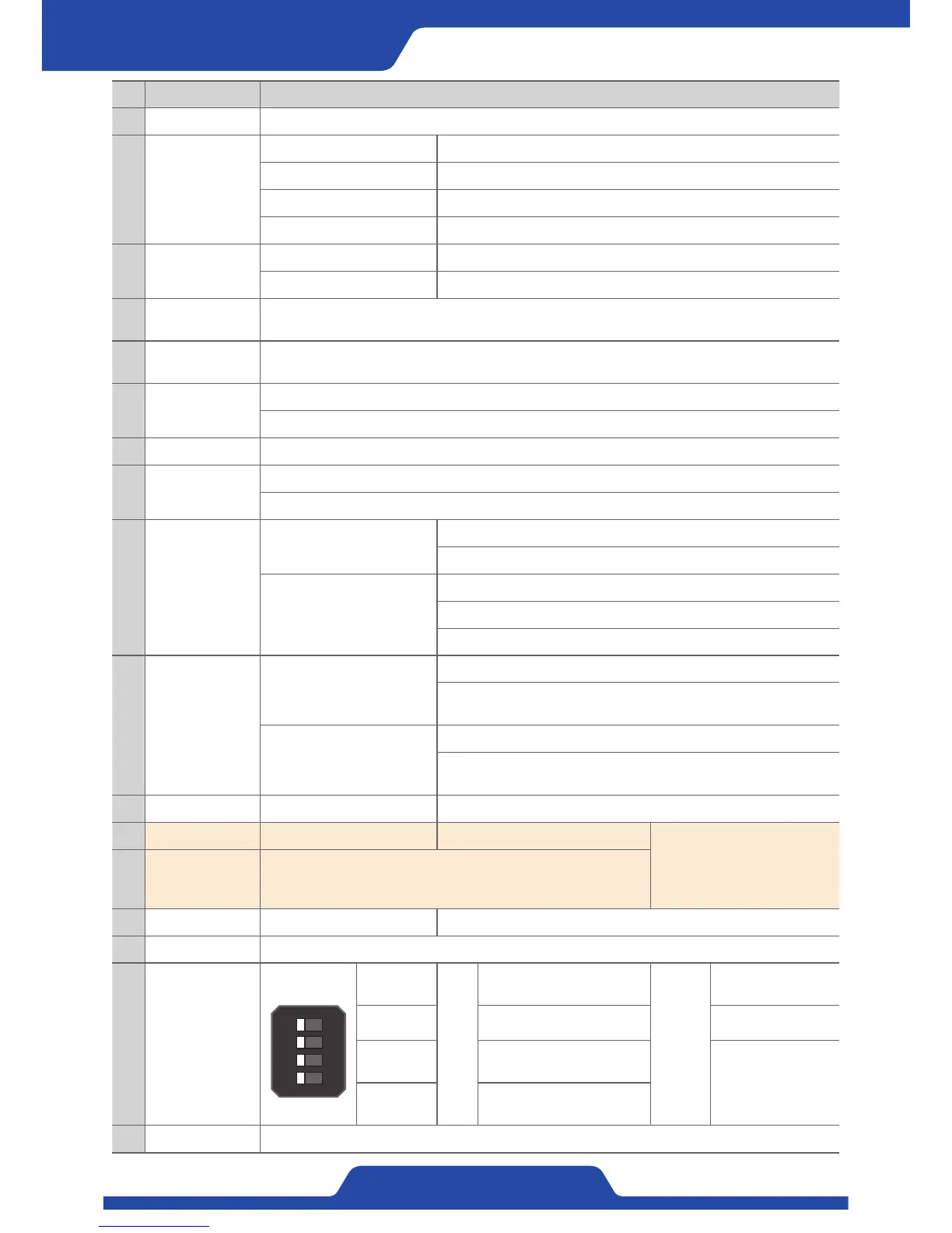
16 Dip switch
1
2
3
4
ONOFF
1. CALI
ON
/
OFF
Selectable P·I·D setting
while on operation.
Remark
-
- - -
3. Ethernet
Setting Ethernet
communication.
When Ethernet, all
Modbus dip switches
are on, it is set to
Modbus use.
4. Modbus
Modbus Modbus-RTU
Communication setting.
17 Power switch It turns on or off the power.
 Loading...