15. DISPLAY
It is able to set the items related to screen display.
1) TENSION DISPLAY: It is to select the way of tension display.
●
Select item: TOTAL, LEFT, RIGHT
- When selecting Left/Right, it is controlled automatically by only using
the tension of relevant tension detector.
2) DECIMAL POINT: It is to set a cipher below decimal point of tension
which is shown on FND.
- Setting range: 1, 0.1, 0.01
3) L OFFSET(% FS): It is to set offset values which will be added to
tension display at a left detector.
- Setting range: 0.0 ~ 100.0
4) L SPAN(xN): It is to set tension display ratio of a left detector.
- Setting range: 0.0 ~ 10.0
5) R OFFSET(% FS): It is to set offset values which will be added to
tension display at a right detector.
- Setting range: 0.0 ~ 100.0
6) R SPAN(xN): It is to set tension display ratio at a right detector.
- Setting range: 0.0 ~ 10.0
7) BRIGHTNESS(%): It is to set brightness of LCD window.
- Setting range: 10.0 ~ 100.0
8) OUTPUT DISPLAY: It is to set the unit of indicating control output.
●
Select item: %, V
- %: Control output is indicated to 0~100%.
- V: Control output is indicated to 0~23.5V.
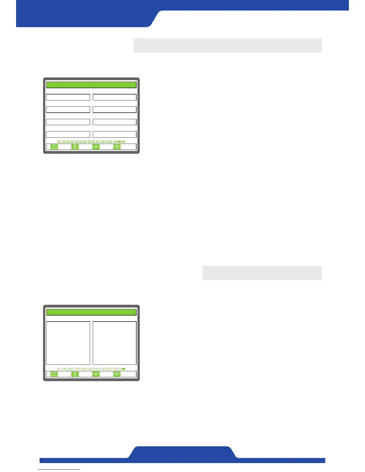
1. TENSION DISPLAY 2. DECIMAL POINT
3. L OFFSET(% FS) 4. L SPAN(xN)
5. R OFFSET(% FS)
0.0
TOTAL
6. R SPAN(xN)
1.0
8. OUTPUT DISPLAY
%
0.0
7. BRIGHTNESS(%)
80.0
1.0
0.1
15. DISPLAY
ESC CLR SET
SELECT
16. INTERFACE CHECK
It is possible to check the internal data of a controller.
1. INTERNAL DATA:
KEY: It shows the data on front buttons.
DIP: It shows setting condition of dip switch in operational part from
board side.
D-IN: It shows the condition of digital input data.
ENC: It shows counter values of switch.
VCC: It shows power condition of +12V inside a controller.
VEE: It shows power condition of -12V inside a controller.
VDD: It shows power condition of +5V inside a controller.
TEMP: It shows temperature of driver board.
SEN1: It shows signal data of a left detector.
SEN2: It shows signal data of a right detector.
SEN3: It shows signal data of a left differential pickup.
SEN4: It shows signal data of a right differential pickup.
A-IN1: It shows data of No. 1 analog input signal.
A-IN2: It shows data of No. 2 analog input signal.
A-IN3: It shows data of No. 3 analog input signal.
A-IN4: It shows data of TG input signal.
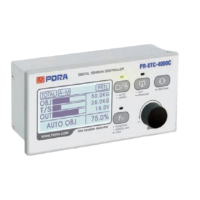
1. INTERNAL DATA X. X. X
KEY :
DIP :
D-IN :
ENC :
PRX :
VCC :
VEE :
VDD :
TEMP :
0x0000
0x0000
0x0000
-5
0
12.0V
-12.0V
4.9V
34.6℃
SEN1 :
SEN2 :
SEN3 :
SEN4 :
A-IN1 :
A-IN2 :
A-IN3 :
A-IN4 :
-147
-167
0
0
0
0
0
0
16. INTERFACE CHECK
ESC CLR SET
SELECT