POWER ELECTRONICS SD450 - DEVICENET
INSTALLATION AND CONNECTION
17
ENGLISH
CONNECTOR
/ LED
DESCRIPTION
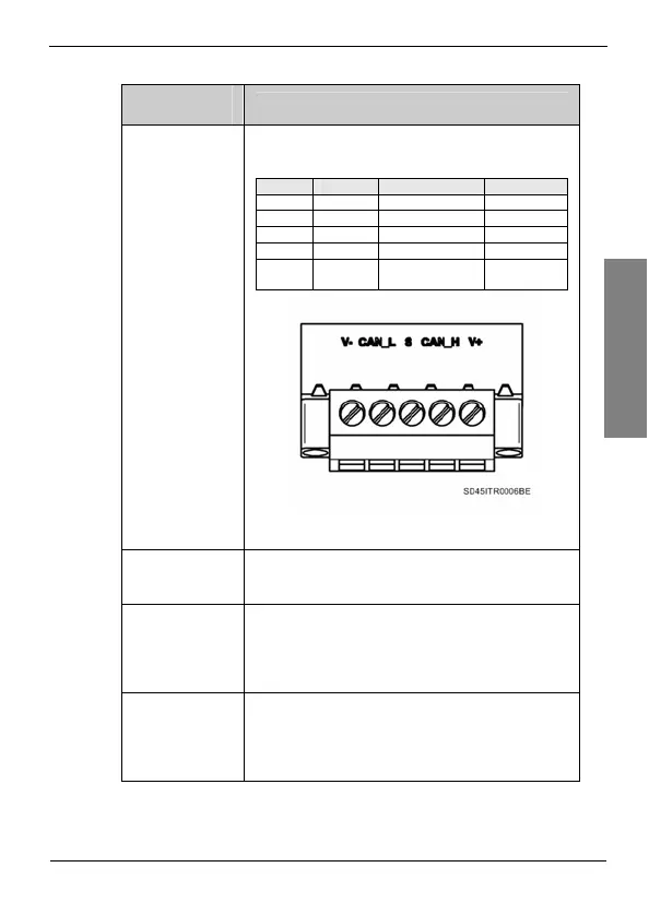
DeviceNet
Connector
(CN2)
Connector for the connections of the specific signals of
DeviceNet network.
Terminal
Signal Function Cable Colour
V- Common Common Black
CAN_L CAN Low Low Signal (-) Blue
S Shield Shield -
CAN_H CAN High High Signal (+) White
V+
Power
Supply
Power Supply
(11 – 24Vdc)
Red
Figure 3.3 Detail of DeviceNet connector
Inverter
Connector
(CN1)
By using it, DeviceNet board is connected to the
inverter.
MS Led
(D1)
Depending on its status (solid / flashing) and its colour
(green / red) supplies information about the connection
of the board to the inverter and the incoming power to
the board. See section ‘6.2. MS Led (Module Status)’ to
obtain more detailed information.
NS Led
(D2)
Depending on its status (solid / flashing) and its colour
(green / red) supplies information about the connection
of the board to the network and the communications
status. See section ‘6.1. NS Led (Network Status)’ to
obtain more detailed information.