___________________________________________________________________________________________________________
Part Number 6300-095D Page 13 of 43
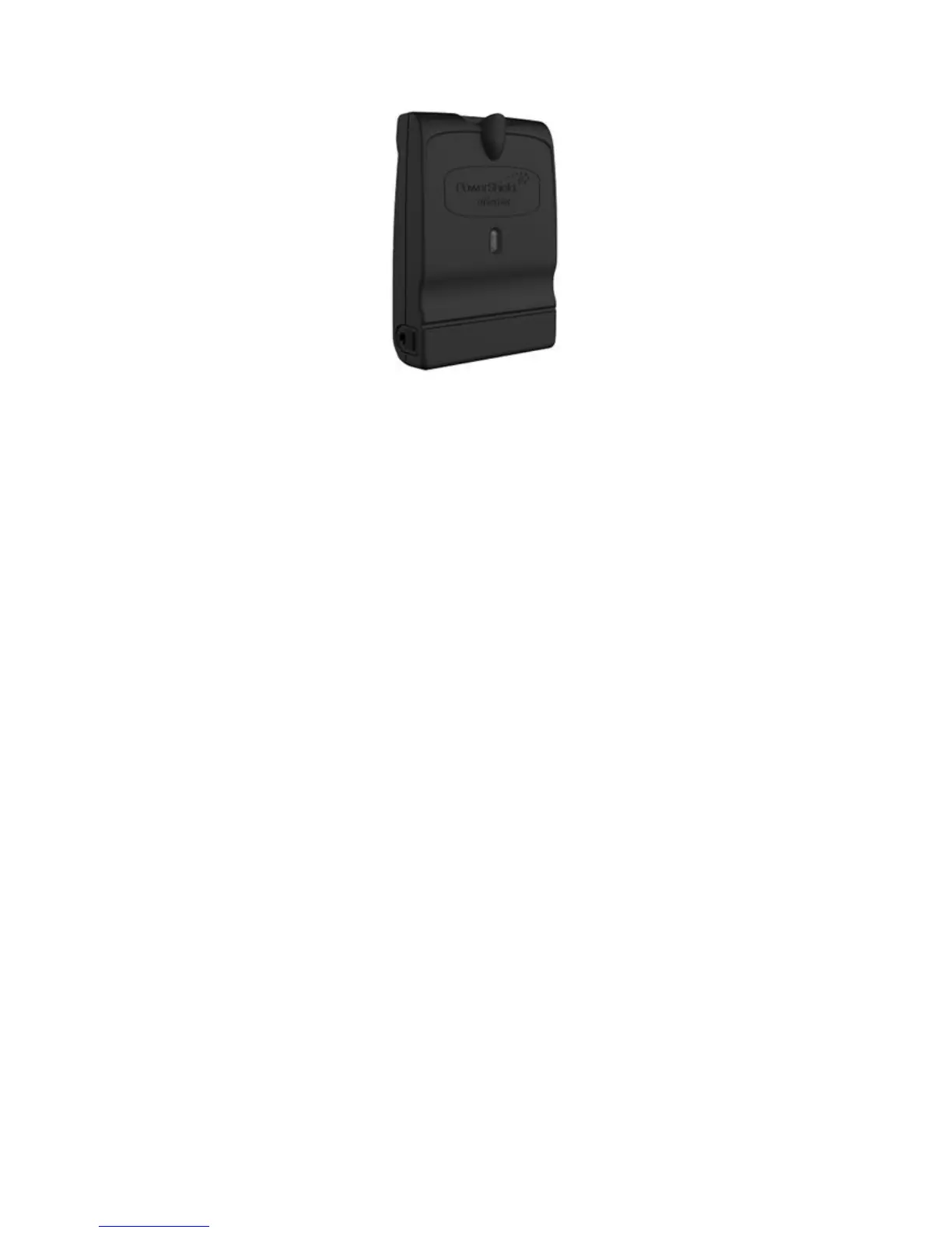
4.4 mSensor
The PowerShield mSensor connects to the blocks and periodically measures the block voltage, temperature and ohmic
value. Each mSensor is specific to the block voltage to which it will be fitted, e.g. 2V / 6V / 12V.
Dual and single mSensors are available. A dual mSensor is used to monitor a pair of blocks located one after another in
series. A single mSensor is used to monitor only one block. The single mSensor allows for installations containing
strings with uneven numbers of blocks or where physical layout makes pairing of blocks impossible. The label on the
mSensor will show whether it is single or dual.
Each mSensor has a factory set ID number. Dual mSensors are numbered with IDs in the range 1 to 200 while single
mSensors are numbered 201 to 220. For ease of mapping of mSensors to blocks and subsequent system configuration,
it is recommended to connect the mSensors to the blocks in sequential order of ID starting at ID 1. Each block in a string
must be uniquely identified with a sequential number starting at 1. For correct automatic mapping of mSensors to blocks,
the block numbering should start at the most positive block in the string. If single mSensors are used in a string, they
should also be installed in sequential order of ID starting at ID 201.
The PowerShield Controller communicates with the mSensors via the Controller hub ports using the BBus daisy chain
communication bus. The mSensors should be connected to the PowerShield Hub using 4-core BBus interconnect cable
via the 4-pin Modular Jack connectors on each device. If a Hub is not used, it is possible to connect the mSensors to the
PowerShield Controller using a Hub-to-BBus adaptor that converts the Controller hub port CAT5 cable to 4-core BBus
interconnect cable.
The LED on the mSensor indicates sensor state. Refer to Appendix 2 for mSensor LED behaviour.