___________________________________________________________________________________________________________
Part Number 6300-095D Page 33 of 43
Appendix 7 – 4-Wire / Kelvin Connection
This article explains the 4-wire or Kelvin connection measurement technique in general terms. It is not intended as an in-
depth guide to making high accuracy measurements of battery impedance.
Resistance
Resistance is commonly measured by passing a known test current through the resistance under test and measuring the
corresponding voltage. The value of resistance is then determined from Ohms law:
R = V/I
where:
R = resistance
V= measured voltage
I = known test current
2-Wire Resistance Measurement
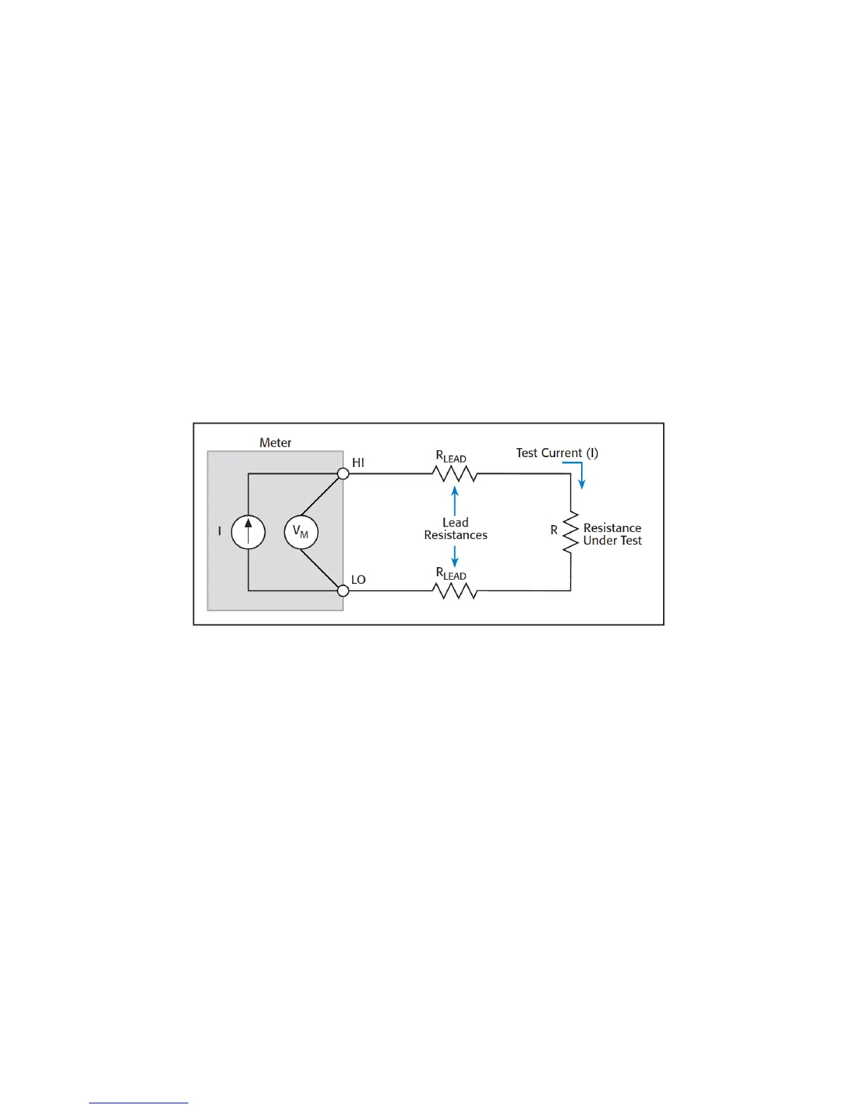
Simple meters measure resistance using 2 leads or probes. Internally, the meter generates a test current that is driven
through the resistance under test while simultaneously measuring the voltage at the terminals of the meter. The diagram
below illustrates this principle.
Note that the meter leads have resistance (denoted R
Lead
above). The points of contact of the meter probes with the
resistance under test also have resistance (denoted R
Contact
, not shown above).
As the meter measures the voltage at its terminals, the voltage developed is due to the total of all resistances in the
external circuit, i.e. R, R
Lead
& R
Contact
. If the lead and contact resistances are significant in value compared to the
resistance under test, the lead and contact resistances result in the meter reporting a higher value for the resistance
under test than its true value.
Example:
Typical meter probes can have resistances in the range 10mΩ to 50mΩ (a 1m length of 20AWG copper wire
has a resistance of approx. 33mΩ). Contact resistance is usually comparable. If the total lead and contact
resistance is 20mΩ and the true value of the resistance under test is also 20mΩ, the meter will report the
resistance to be 40mΩ. Thus, the resistance measurement error is 20mΩ or 100% (20mΩ / 20mΩ).
NOTES:
• Some meters try to compensate for the lead and contact resistances using a Null or Calibration function.
These functions require making a resistance measurement with either the tips of the probes shorted together
or placed across a known, calibrated resistance or shunt. The measured value is then subtracted from
subsequent measurements.
• Meters using the 2-wire method are generally only capable of measuring resistance to just under 1Ω with
accuracy of about 50 to 100mΩ as they do not have adequate accuracy or resolution.