___________________________________________________________________________________________________________
Part Number 6300-095D Page 21 of 43
Appendix 1 – Controller Panels
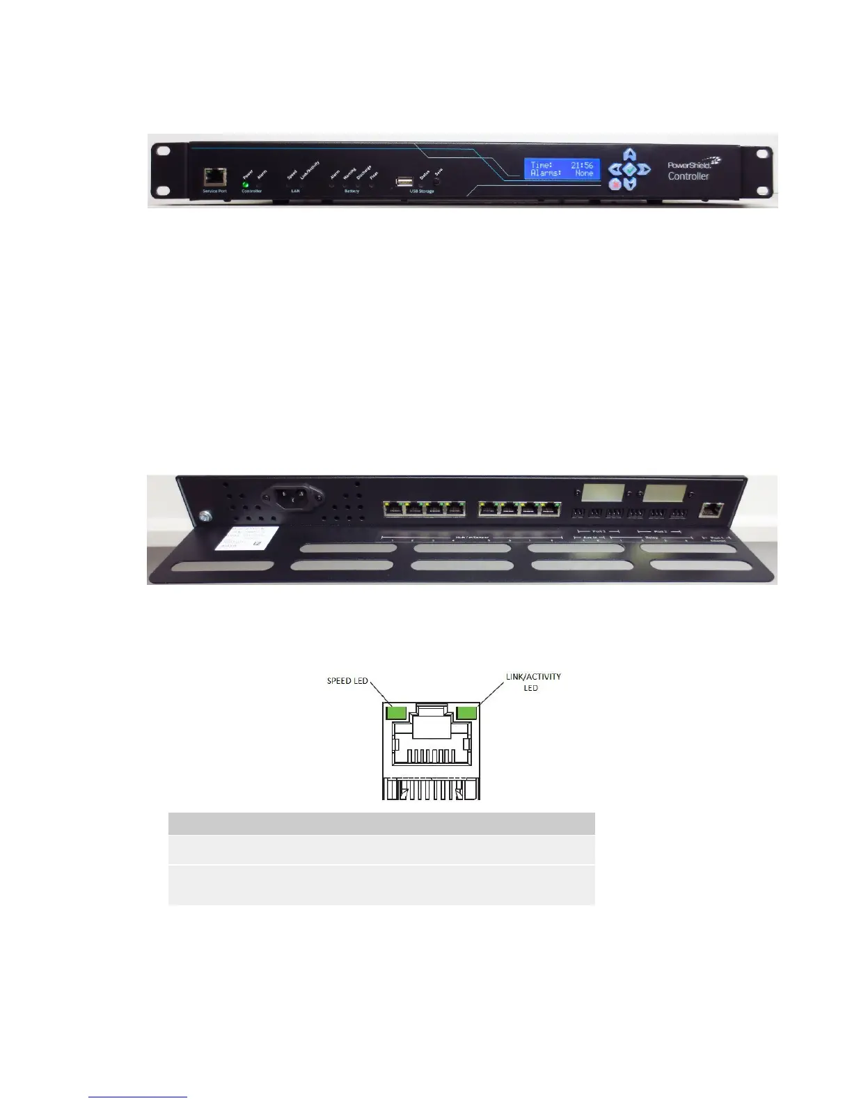
Front Panel
The front panel has the following features:
• Service Port: This is an Ethernet port that can be used to temporarily connect to the PowerShield Controller
on site.
• LEDs: These indicate system behaviour. Refer to Appendix 2 for a description of the LED states.
• USB Port: The USB Port can be used to copy Controller data and configuration files to a USB Flash Drive.
• USB Save Button: This button is used to start the copying of files to the USB Flash Drive.
• LCD: The LCD displays some system information. Navigation is via the 6-key keypad. Refer to Appendix 3
for a description of the LCD menu system and information displayed.
Rear Panel
The rear panel has the following features (viewed from right to left):
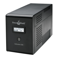
• Port 1: This is an Ethernet port that is intended as a permanent LAN connection for the PowerShield
Controller. The behaviour of the LEDs are as follows:
Speed Green On if LAN connection is operating at 1Gbps.
Link/Activity Green On if LAN Ethernet link is up.
Flashes during activity.
• Port 2 & 3: These ports are for optional communication devices. Refer to Appendix 4 for more details.
• Relays: The PowerShield Controller has 4 relays that can be used to control or trigger external devices when
certain events occur. Refer to Appendix 5 for details of the relay terminals.
• Auxiliary Inputs: The PowerShield Controller has 2 dry contact inputs that can be used to read the state of
external devices. Refer to Appendix 5 for details of the Auxiliary Inputs.