___________________________________________________________________________________________________________
Part Number 6300-095D Page 28 of 43
Appendix 6 – mSensor Power Lead Connection
It is important to connect and install the mSensor power lead correctly. The following diagrams show the recommended
method of connecting an mSensor to blocks with 2 or 4 terminals per block.
Failure to connect and install the mSensor power lead correctly may lead to unacceptable variation in readings between
sensors.
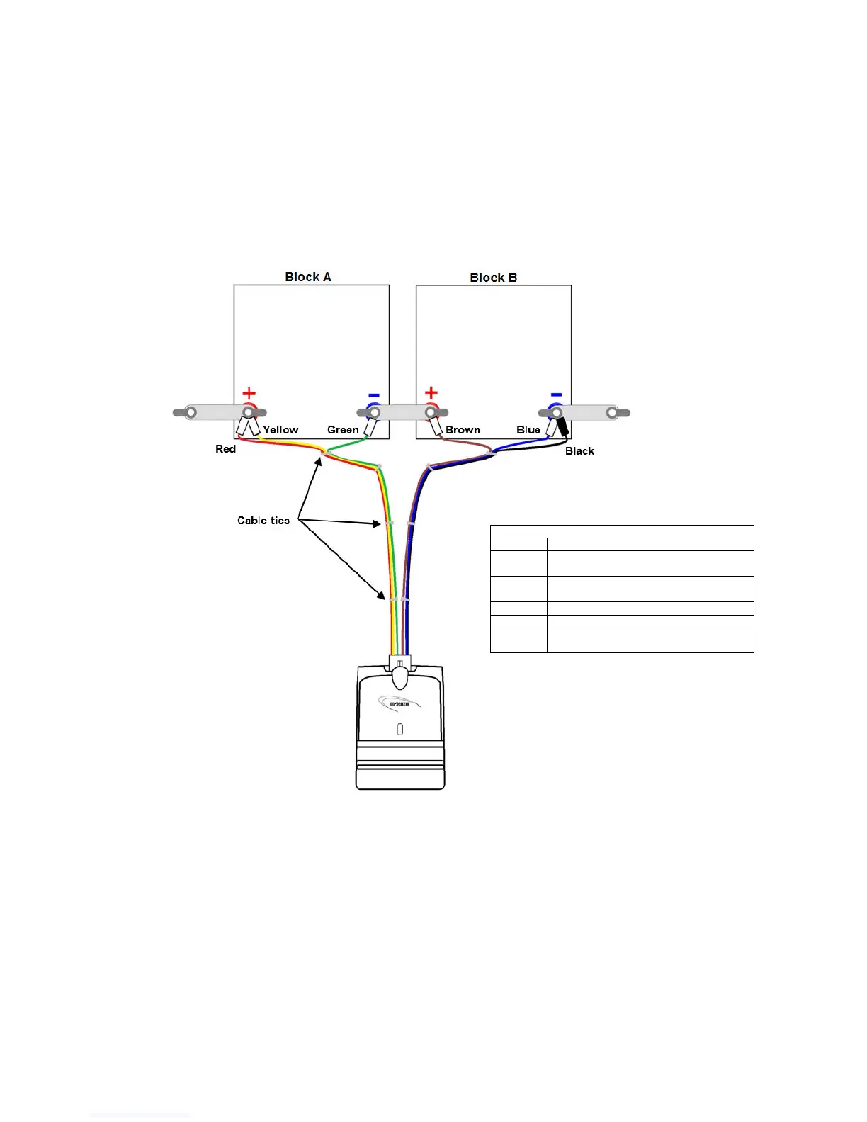
Dual mSensor and Blocks with 2 Terminals
Red Positive Power wire for sensor.
Connect to positive terminal of Block A.
Yellow Positive Sense wire for Block A.
Green Negative Sense wire for Block A.
Brown Positive Sense wire for Block B.
Blue Negative Sense wire for Block B.
Black Power return wire for sensor.
Connect to negative terminal of Block B.
Please note the following important points:
• The power lead is manufactured with cable ties in order to keep the Sense wire pairs and the Power wires
closely coupled.
• Try to keep the Sense wire pairs and Power wires closely coupled as much as possible.
• Where possible, do not remove the cable ties.
• The cable ties nearest the block terminals may be need to be repositioned to allow the wires to be
connected to the block terminals.
• Do not connect the Green and Brown Sense wires to the terminal of one block. Connect them to the
positive and negative terminals of the respective blocks.