___________________________________________________________________________________________________________
Part Number 6300-095D Page 26 of 43
Appendix 4 – Communication Options
The PowerShield Controller has two internal slots for optional communication cards. The connectors for these cards will
be fitted to the Port 2 or Port 3 openings in the rear panel.
These cards offer an optional way of communicating with the PowerShield Controller using a MODBUS RTU protocol.
Refer to the PowerShield Controller User Manual (part number 6300-103) for details of how to configure the cards.
RS-485
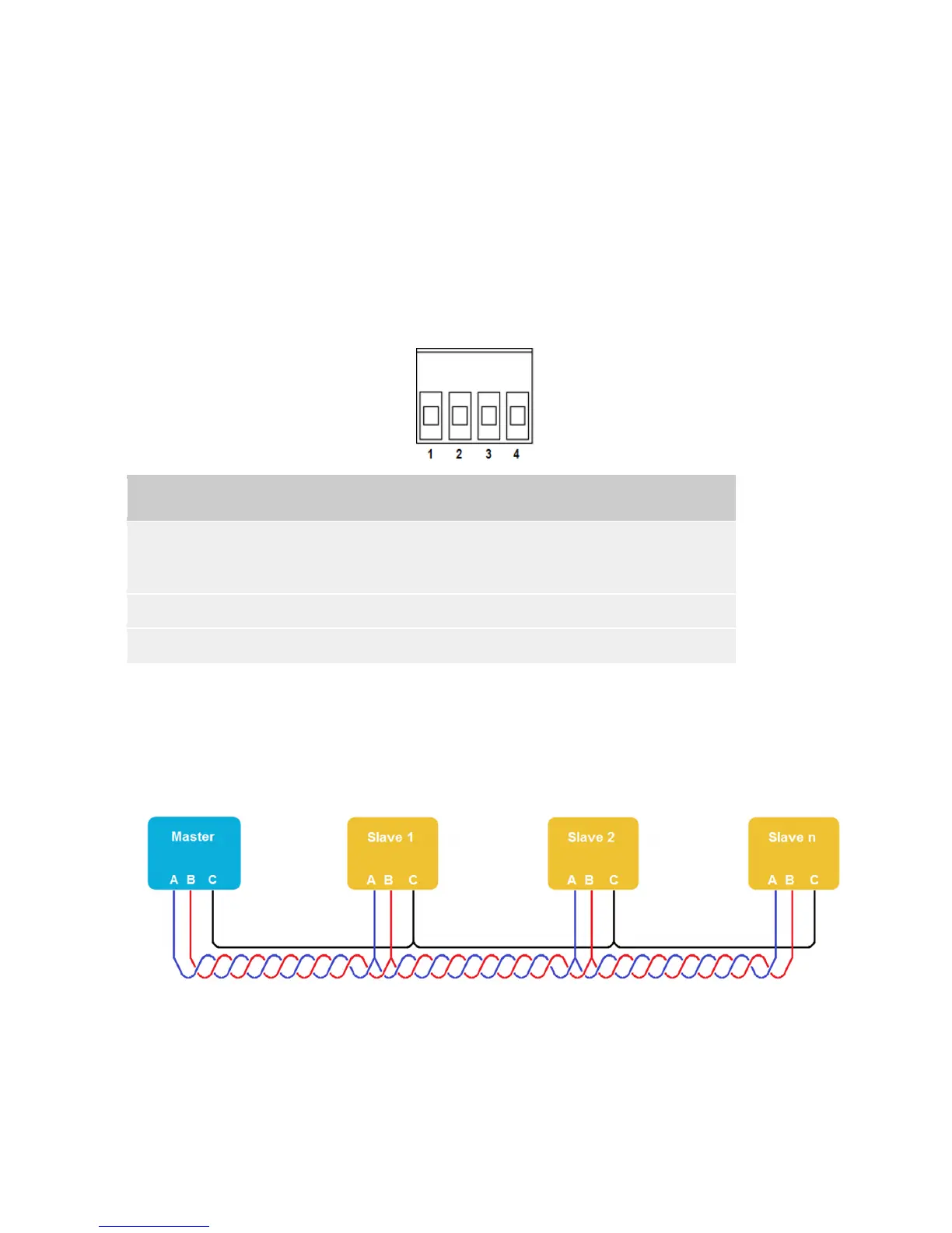
The RS-485 card implements 2-wire (half-duplex) transmission. The RS-485 signals can be accessed at the 4-way
screw terminal connector on the rear panel of the PowerShield Controller as shown below. If more than one Slave is on
the RS-485 bus, connect the additional Slaves using a daisy-chain approach and join the signal wires at the 4-way
connector.
Pin Name Function
1, 4 Common (C) Common signal reference ground for RS-485 differential pair.
This should be connected to the ground of the Master device for correct
signal level translation and to limit common mode voltages.
2 Data+ (B) Positive signal of RS-485 differential data pair.
3 Data- (A) Negative signal of RS-485 differential data pair.
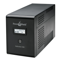
Cabling & Termination
The diagram below illustrates a RS-485 Master with multiple Slaves.
It is recommended to use twisted pair wire for the RS-485 signals for improved noise immunity.
For long cable runs or where signal reflections are an issue, it is good practice to terminate the signal wires at each end
of the cable with a resistor equal to the characteristic impedance of the cable. A typical value for 24 AWG twisted pair
cable is 120Ω.
To terminate the cable at the PowerShield Controller, fit a suitable resistor between pins 2 & 3 of the 4-way connector.