Do you have a question about the Powtran PI7500 Series and is the answer not in the manual?
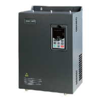
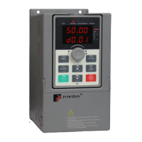
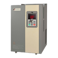
Checks contents, nameplate, and model designation upon receiving the inverter.
Essential safety guidelines for operating and handling the frequency inverter.
Describes typical applications and potential risks associated with the inverter.
Specifies environmental and operational conditions for installing the frequency inverter.
Provides guidelines for installing the frequency inverter with adequate ventilation.
Details the main and control circuit wiring for the frequency inverter.
Lists and explains the main circuit terminals of the PI7500 inverter.
Provides a table of terminal functions for power input and motor connection.
Introduces the control circuit terminals and their distribution.
Detailed explanation of each control circuit terminal and its function.
Important precautions to follow during the connection and installation process.
Describes how to add a standby circuit to prevent loss during faults.
Explains the availability and switching of internal and external keyboards.
Details the specifications and functions of the PI7500 internal operating keyboard.
Introduces optional external keyboards and their specifications.
Describes the JP3E7000 external keyboard's specifications and functions.
Details the JP5E7000 external keyboard's specifications and functions.
Explains the JP6E7000 and JP6C7000 keyboard specifications and functions.
Explains the functions of keys like RUN, STOP/RESET, Parameter Alternation, Escape/Display, and Jog.
Provides an example of how to modify parameter values using the keyboard.
Step-by-step guide on modifying an acceleration time parameter.
Example of test running with analog voltage input and mixed control.
Example of test running using keyboard for speed and operation control.
Table listing basic parameters of the inverter with their ranges and settings.
Details parameter F05 for controlling the inverter's running mode.
Parameter F06 for selecting the PWM waveform occurrence mode.
Parameter F07 for improving low-frequency performance and voltage boost.
Parameter F08 for selecting different V/F boost modes.
Parameter F09 for setting acceleration time from 0Hz to max frequency.
Parameter F10 for setting deceleration time from max frequency to 0Hz.
Parameter F11 for compensating motor slip.
Parameter F12 to adjust output voltage percentage.
Parameter F13 for setting the maximum output frequency.
Parameter F14 for setting the basic frequency for motors.
Parameter F15 for reducing noise and vibration.
Parameter F16 for setting the lower limit of output frequency.
Parameter F17 for setting the upper limit of output frequency.
Parameter F18 for setting the start time of S-curve acceleration.
Parameter F19 for setting the S-curve acceleration stop time.
Parameter F20 for setting the start time of S-curve deceleration.
Parameter F21 for setting the stop time of S-curve deceleration.
Parameter F22 for setting the minimum frequency for the motor to run.
Parameter F23 for setting the DC braking current percentage.
Parameter F24 for setting the DC braking time during starting.
Parameter F25 for setting the DC braking time during stopping.
Parameter F26 for setting the frequency for DC braking start.
Parameter F27 for selecting the stop mode (deceleration or free stop).
Parameter F28 for setting jog acceleration time.
Parameter F29 for setting jog deceleration time.
Parameter F30 for setting the jog direction.
Parameter F31 for setting the jog frequency.
Parameter F32 for setting the first traverse running frequency.
Parameter F33 for setting the second traverse running frequency.
Parameter F34 for setting the traverse running difference.
Parameter F35 for setting the first traverse running timing.
Parameter F36 for setting the second traverse running timing.
Parameter F37 for setting the first skip frequency.
Parameter F38 for setting the second skip frequency.
Parameter F39 for setting the third skip frequency.
Parameter F40 for setting the skip frequency range.
Parameter F41 for automatic voltage regulation.
Parameter F42 for over voltage stall protection.
Parameter F43 for current limit function.
Parameter F44 for selecting the pick up mode.
Parameter F45 for electronic thermal relay protection selection.
Parameter F46 for setting the electronic thermal relay protection level.
Parameter F47 for selecting power consuming braking.
Parameter F48 for setting the number of fault reset times.
Parameter F49 for setting the fault auto-reset time.
Parameter F50 for selecting the program running mode.
Parameter F51 for setting the restart mode after stopping.
Parameter F54 for setting the motor running direction.
Parameter F55 for forbidding motor reverse.
Parameter F56 for setting the running time unit.
Parameter F57 for setting energy saving running percentage.
Parameter F58 for setting the first FDT frequency.
Parameter F59 for setting the second FDT frequency.
Parameter F60 for setting the frequency inspection range.
Parameter F61 for selecting the load type.
Parameter F62 for selecting terminal control modes.
Parameter F63 for MSS multi-step speed or acceleration control.
Parameter F64 for selecting input terminal polarity.
Parameter F65 for selecting the second monitored object.
Parameter F66 for selecting the third monitored object.
Parameter F67 for setting the V/F curve.
Parameter F68 for controlling MSS multi-step speed.
Parameter F69 for selecting the I/O group.
Parameter F70 for selecting the CUR group.
Parameter F71 for selecting the SPD group.
Parameter F72 for selecting the PID group.
Parameter F73 for selecting the SYS group.
Parameter F74 for selecting the MOT group.
Parameter F01 to select the inverter's control mode.
Parameter F02 for setting the running frequency.
Parameter F03 for setting the frequency display accuracy.
Parameter F04 for selecting the frequency setting method.
Parameter F05 for selecting the running control mode (keypad or terminal).
Parameter F06 for selecting the PWM waveform occurrence mode.
Parameter F07 for improving low-frequency performance and voltage boost.
Parameter F08 for selecting different V/F boost modes.
Parameter F09 for setting acceleration time from 0Hz to max frequency.
Parameter F10 for setting deceleration time from max frequency to 0Hz.
Parameter F11 for compensating motor slip.
Parameter F12 to adjust output voltage percentage.
Parameter F13 for setting the maximum output frequency.
Parameter F14 for setting the basic frequency for motors.
Parameter F15 for reducing noise and vibration.
Parameter F16 for setting the lower limit of output frequency.
Parameter F17 for setting the upper limit of output frequency.
Parameter F18 for S-curve acceleration start time.
Parameter F19 for S-curve acceleration stop time.
Parameter F20 for setting the start time of S-curve deceleration.
Parameter F21 for setting the stop time of S-curve deceleration.
Parameter F22 for setting the minimum frequency for the motor to run.
Parameter F23 for setting the DC braking current percentage.
Parameter F24 for setting the DC braking time during starting.
Parameter F25 for setting the DC braking time during stopping.
Parameter F26 for setting the frequency for DC braking start.
Parameter F27 for selecting the stop mode.
Parameter F28 for setting jog acceleration time.
Parameter F29 for setting jog deceleration time.
Parameter F30 for setting the jog direction.
Parameter F31 for setting the jog frequency.
Parameter F32 for setting the first traverse running frequency.
Parameter F33 for setting the second traverse running frequency.
Parameter F34 for setting the traverse running difference.
Parameter F35 for setting the first traverse running timing.
Parameter F36 for setting the second traverse running timing.
Parameter F37 for setting the first skip frequency.
Parameter F38 for setting the second skip frequency.
Parameter F39 for setting the third skip frequency.
Parameter F40 for setting the skip frequency range.
Parameter F41 for automatic voltage regulation.
Parameter F42 for over voltage stall protection.
Parameter F43 for current limit function.
Parameter F44 for selecting the pick up mode.
Parameter F45 for electronic thermal relay protection selection.
Parameter F46 for setting the electronic thermal relay protection level.
Parameter F47 for selecting power consuming braking.
Parameter F48 for setting the number of fault reset times.
Parameter F49 for setting the fault auto-reset time.
Parameter F50 for selecting the program running mode.
Parameter F51 for setting the restart mode after stopping.
Parameter F54 for setting the motor running direction.
Parameter F55 for forbidding motor reverse.
Parameter F56 for setting the running time unit.
Parameter F57 for setting energy saving running percentage.
Parameter F58 for setting the first FDT frequency.
Parameter F59 for setting the second FDT frequency.
Parameter F60 for setting the frequency inspection range.
Parameter F61 for selecting the load type.
Parameter F62 for selecting terminal control modes.
Parameter F63 for MSS multi-step speed or acceleration control.
Parameter F64 for selecting input terminal polarity.
Parameter F65 for selecting the second monitored object.
Parameter F66 for selecting the third monitored object.
Parameter F67 for setting the V/F curve.
Parameter F68 for controlling MSS multi-step speed.
Parameter F69 for selecting the I/O group.
Parameter F70 for selecting the CUR group.
Parameter F71 for selecting the SPD group.
Parameter F72 for selecting the PID group.
Parameter F73 for selecting the SYS group.
Parameter F74 for selecting the MOT group.
Troubleshooting steps when the keyboard is unresponsive.
Troubleshooting steps when the potentiometer fails to regulate speed.
Diagnosing issues when the motor fails to rotate.
Explains various over current fault displays and their causes.
Discusses over voltage faults, their causes, and solutions.
Addresses low voltage faults, their causes, and solutions.
Covers overheat faults, their causes, and solutions.
Table detailing electrical specifications of the inverter by voltage and power.
Lists standard specifications for control, input, and output signals.
Provides dimensional drawings and specifications for the inverter's physical size.
Details physical dimensions and mounting information for external keyboards.
Outlines regular inspection and maintenance procedures for the inverter.
Lists parts that require periodic replacement and their intervals.
Provides guidelines for storing the frequency converter when not in use.
Explains how to measure and judge inverter performance using instruments.
Explains the function of MCCB or ELCB as a power switch.
Describes the purpose and selection of noise filters.
Explains the function of connectors for system protection.
Details how to select braking resistors for the braking unit.
| Cooling Method | Forced air cooling |
|---|---|
| Output Voltage | 0V to Input Voltage (3-phase) |
| Power Range | 0.75kW to 630kW |
| Control Mode | V/F control, Sensorless Vector Control (SVC), Closed-loop Vector Control (VC) |
| Overload Capacity | 150% rated current 60s; 180% rated current 10s |
| Speed Adjusting Range | 1:100 (SVC); 1:1000 (VC) |
| Frequency Resolution | 0.01Hz |
| Communication | RS485 |
| Input Frequency | 50/60Hz |
| Protection Features | Over-current, over-voltage, under-voltage, over-heat, overload, phase loss |
| Operating Temperature | -10°C to +50°C |
| Storage Temperature | -20~60℃ |
| Humidity | ≤95% RH (non-condensing) |
| Altitude | Lower than 1000m; The derating is required if the altitude exceeds 1000m |