© Precor Incorporated, Unauthorized Reproduction and Distribution Prohibited by Law Page 71
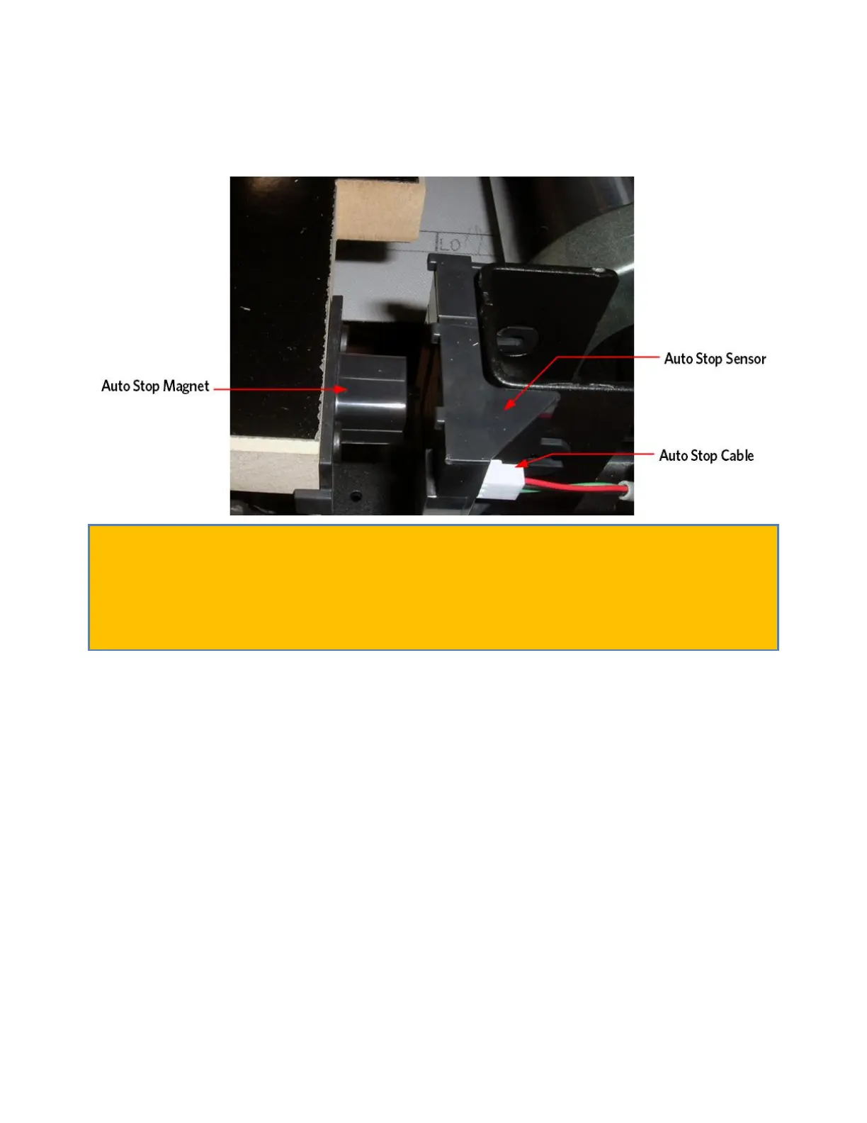
Figure 17: Auto Stop Assembly
Caution: Do not place the auto stop magnet on or near a steel
structure. If the magnet assembly comes in contact with a steel
structure and then pulled away from the steel structure, the magnet can
become dislodged from the magnet assembly housing. Should this occur,
contact PRECOR customer service for possible options for repairing the
magnet assembly or to obtain a replacement part.
8 The Auto Stop system consists of a magnet holder mounted to the
right front corner of the deck and a Hall Effect sensor mounted to
the drive roller bracket of the frame. Check the alignment and gap
(3/16") between the Auto Stop magnet holder and the Auto Stop
sensor. If the alignment and gap are not correct, it may be
necessary to loosen the deck and adjust so that the magnet is gapped
and positioned properly relative to the sensor. Reference Procedure,
Replacing the Auto Stop Magnet. If the alignment and the gap between
the Auto Stop magnet holder and the Auto Stop sensor are correct
continue with step 9.
9 The Auto Stop sensor will display a green blinking LED visible next
to the connector, indicating that power is being applied to the
sensor board. The LED does not tell you if the voltage is correct,
just that it is present. If the LED is not lit or if LED is lit
continue with step 9. See Figure Below.