© Precor Incorporated, Unauthorized Reproduction and Distribution Prohibited by Law Page 72
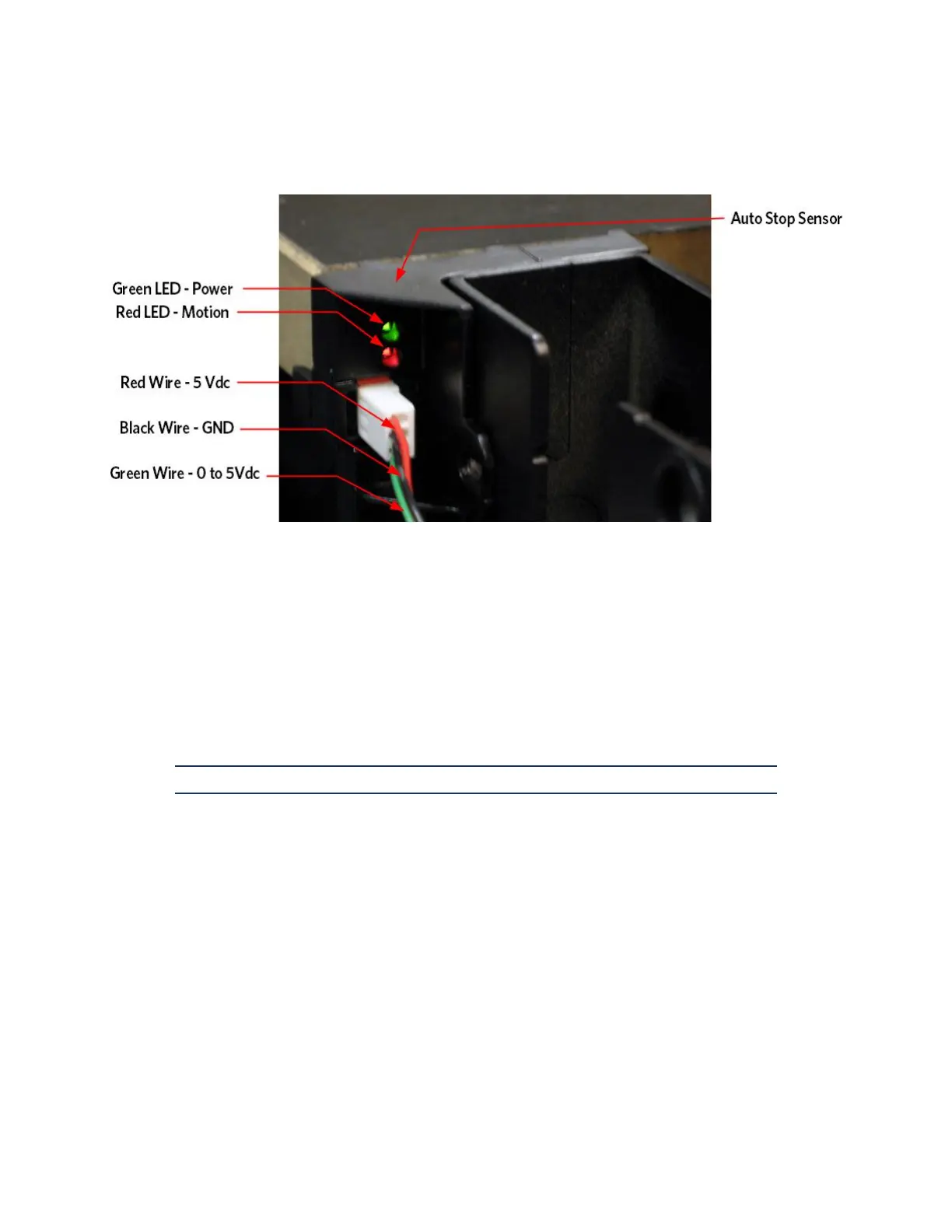
Figure 18: Auto Stop LED's and Wire Connector
10 The connector has 3 wires (red, black, and green), which can be
metered for troubleshooting. Unplug the Auto Stop connector from the
Auto Stop Sensor.
11 Place the meter’s red lead to the red wire and black lead to the
black wire of the Auto Stop connector. The meter should indicate 5
volts +/- 0.1 volt. If 5 volts is present skip to step 12.
12 If the 5 volts is not present of significantly low temporarily
replace the Auto Stop cable with a known good cable and repeat step
10. If the 5 volts is not present or the voltage is still
significantly low replace the console or upper PCA. If 5 volts is
present permanently replace the Auto Stop cable.
Note: The running belt does not need to be moving for this test.
13 With the Auto Stop connector plugged into the Auto Stop sensor place
the meter’s red lead to the green wire and black lead to the black
wire. The meter should indicate 5 volts +/- 0.1volt. While
monitoring this voltage, have someone step and/or bounce on the deck
The voltage between the black and green wires should fluctuate when
the deck is moving up and down. If the voltage does not change with
movement replace the Auto Stop Sensor.
14 If you have preformed all the described steps and the Auto Stop
feature will still not function contact Precor Customer Support.