Pos. Name Description
4 TTC48-3 Control unit: Input/Output rear lift frame, blade, tiller
5 TTC30 Heating control unit
6 A43 Wiper control unit
To avoid damaging the control units when connecting and disconnecting, follow the instructions below:
■ Control
unit connectors should only be disconnected or connected when the electrical system
(master switch OFF) is switched off.
■ Reversing the polarity may destroy the control units.
■ Only start the engine if the batteries are connected firmly.
■ Do not disconnect the batteries while the engine is running.
■ Only start the engine if the rpm sensor is connected.
■ Do not use a quick-charger to start the engine; only use external batteries to assist starting.
■ To quick-charge the batteries, disconnect the battery terminals.
■ Follow the user instructions for the quick-charger.
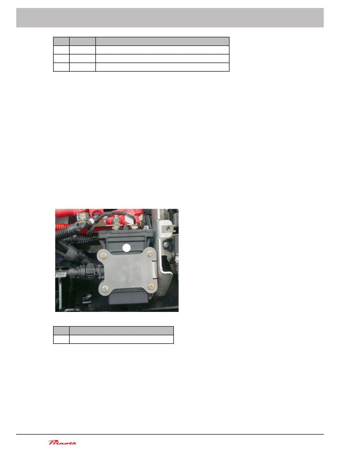
Battery disconnect switch
The battery disconnect switch is located under the right access panel of the rear cowling. This switch
connects or disconnects the batteries to prevent discharge. Operation of the switch is automatic but
there is an override control in the cab.
Figure 27: Under the right access panel of the rear cowling
Pos. Name
1 Battery disconnect switch in the cowling
Functioning
The switch turns on when the key is inserted and turned ON in the ignition switch of the cab.
The switch turns off with a 6 min delay when the key is turned to OFF in the ignition switch of the cab.
The delay is required to permit a normal shutdown of the engine and its electronic systems.
Operating and Maintenance Manual
Snow groomer BISON
72 (255)
5 - Vehicle
BISON 908930245 - 30367
5.13
■