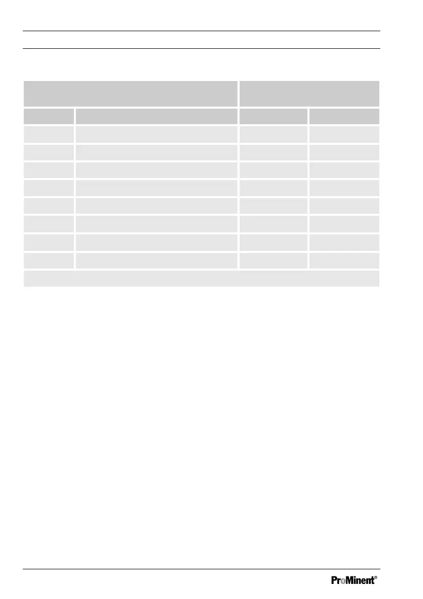
Connection of the measured vari‐
able to:
Character Measured variable mV input mA input
H H
2
O
2
(hydrogen peroxide) X
I Chlorite X
P pH X X*
R ORP X X*
S 0/4...20 mA standard signal general X
X O
2
X
Z O
3
X
L Conductivity X
*with measured value transducer
Description of the terminal connections for mA and mV: see Fig. 11 and Fig. 12
Description of the operating menu of the measured variables via mV connection:
see
Ä Chapter 8 ‘Measured Variables and Operating Menus for Potentiometric Sensors’
on page 81
Description of the operating menu of the measured variables via mA connection: see
Ä Chapter 7 ‘Measured Variables and Operating Menus for Amperometric Sensors’
on page 69
Description of the operating menu of the measured variables via mA standard signal: see
Ä Chapter 9 ‘Measured Variables and Operating Menus for the Standard Signal General’
on page 101
2.1 Wall mounting/control panel
installation
DULCOMETER
®
D1Cb
The DULCOMETER
®
D1Cb W is suitable
both for wall-mounting, as well as for
installation in a control panel (with addi‐
tional control panel mounting kit).
The plastic housing comprises a housing
upper section and lower section. The LCD
display and membrane keypad are
accommodated in the upper section of the
housing.
The lower section of the housing accom‐
modates the processor and power units
and any optional assemblies. A ribbon
cable connects to the LCD display and the
membrane keypad.
Functional description
18