OPTALIGN smart RS5 BT handbook
134
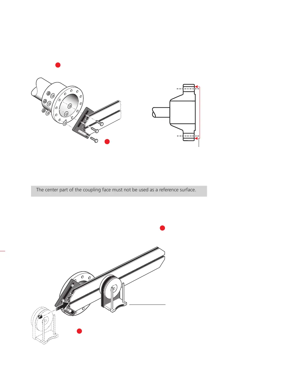
3. Mount the bracket assembly to the coupling face of the non-rotatable shaft. If
the coupling face has a raised rim, the precision machined spacers are used as
shown [
3
] in order to separate the bracket faceplate from the coupling face.
(Without the spacers, there would be no direct contact between the faceplate and the
coupling surface surrounding the bolt holes – exactly the location where the faceplate
and coupling are being joined.)
The center part of the coupling face must not be used as a reference surface.
7.2.2 Mounting the laser holder assembly on to the rail
1. Loosen the handwheel slightly, then slide the laser holder assembly down the
center groove of the rail, with the T-nut acting as a guide [
1
].
The coupling shown
opposite has a raised
face flange. The provided
spacers are used to create
a three-point plane to
ensure that the faceplate
and the coupling face,
which is the reference
surface are joined
together.
Reference surface
3
HNote
1
RS5 laser holder