OPTALIGN smart RS5 BT handbook
148
7.4 Measure
1. Press m and then establish wireless communication between the sensor and
OPTALIGN smart computer ( refer to ‘Wireless measurement’ in section 4.4).
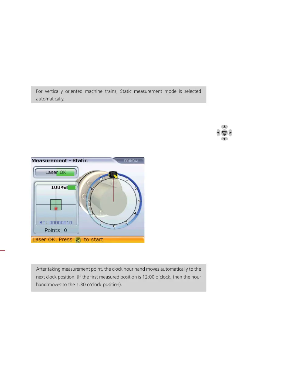
For vertically oriented machine trains, Static measurement mode is selected
automatically.
2. Center laser beam as described in ‘Laser beam adjustment’ in section 5.9.
3. Rotate the shafts to the first measurement position. The reference mark and the
measurement position 0 must be aligned with each other. Use the navigation
keys to place the screen hour hand (red cursor line) to correspond with the
position of the laser and sensor on the shafts.
4. Press
e to take the first measurement point.
After taking measurement point, the clock hour hand moves automatically to the
next clock position. (If the first measured position is 12:00 o’clock, then the hour
hand moves to the 1.30 o’clock position).
5. Rotate the shafts to the second measurement position (this could be either
1:30, 3.00, 4.30, 6.00, 7.30, 9.00 or 10.30 o’clock position). If particular
measurement positions are to be bypassed (say due to shaft rotation restrictions),
use the navigations keys and move the screen hour hand (red cursor line) to
correspond to the new position of the laser and sensor on the shafts. Press
e
to take measurement point.
H
Note
H
Note