Horizontal shaft alignment
85
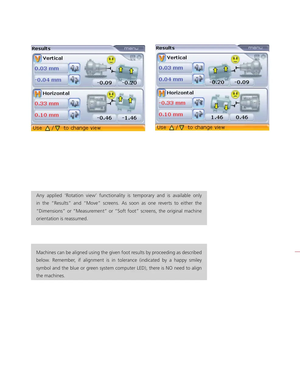
The screen on the left shows the initial orientation as viewed by the user, while the
screen on the right shows the orientation after the ‘Rotation view’ function has been
applied. In the screen on the right, the machine designated stationary is now on
the right hand side. Note that the vertical coupling gap values for both orientations
remains unaltered as are the horizontal coupling offset values. The applied sign con-
vention holds valid for both orientations.
Any applied ‘Rotation view’ functionality is temporary and is available only
in the “Results” and “Move” screens. As soon as one reverts to either the
“Dimensions” or “Measurement” or “Soft foot” screens, the original machine
orientation is reassumed.
5.13 Align machine
Machines can be aligned using the given foot results by proceeding as described
below. Remember, if alignment is in tolerance (indicated by a happy smiley
symbol and the blue or green system computer LED), there is NO need to align
the machines.
To align your machine you need to move it vertically by shimming the feet, and
horizontally by shifting it sideways. You could do these operations in either order or
simultaneously, but the recommended procedure is as follows:
HNote
HNote