143
For circular housings, measure the circumference of the bearing housing and divide by
eight. Use this distance to make eight evenly-spaced marks on the housing
beginning at your chosen start point. Number the points clockwise looking
down onto the shaft with 0 as the first, followed by 1:30, 3:00, 4:30, 6:00,
7:30, 9:00 and 10:30. (Refer to the diagram opposite.)
7.3.3 Mounting components and selecting machine orientation
1. Mount the sensor with the integrated Bluetooth, and the laser on either
side of the coupling, ensuring that they are aligned exactly with the 0 or
reference mark.
2. Switch OPTALIGN smart computer on by pressing
e.
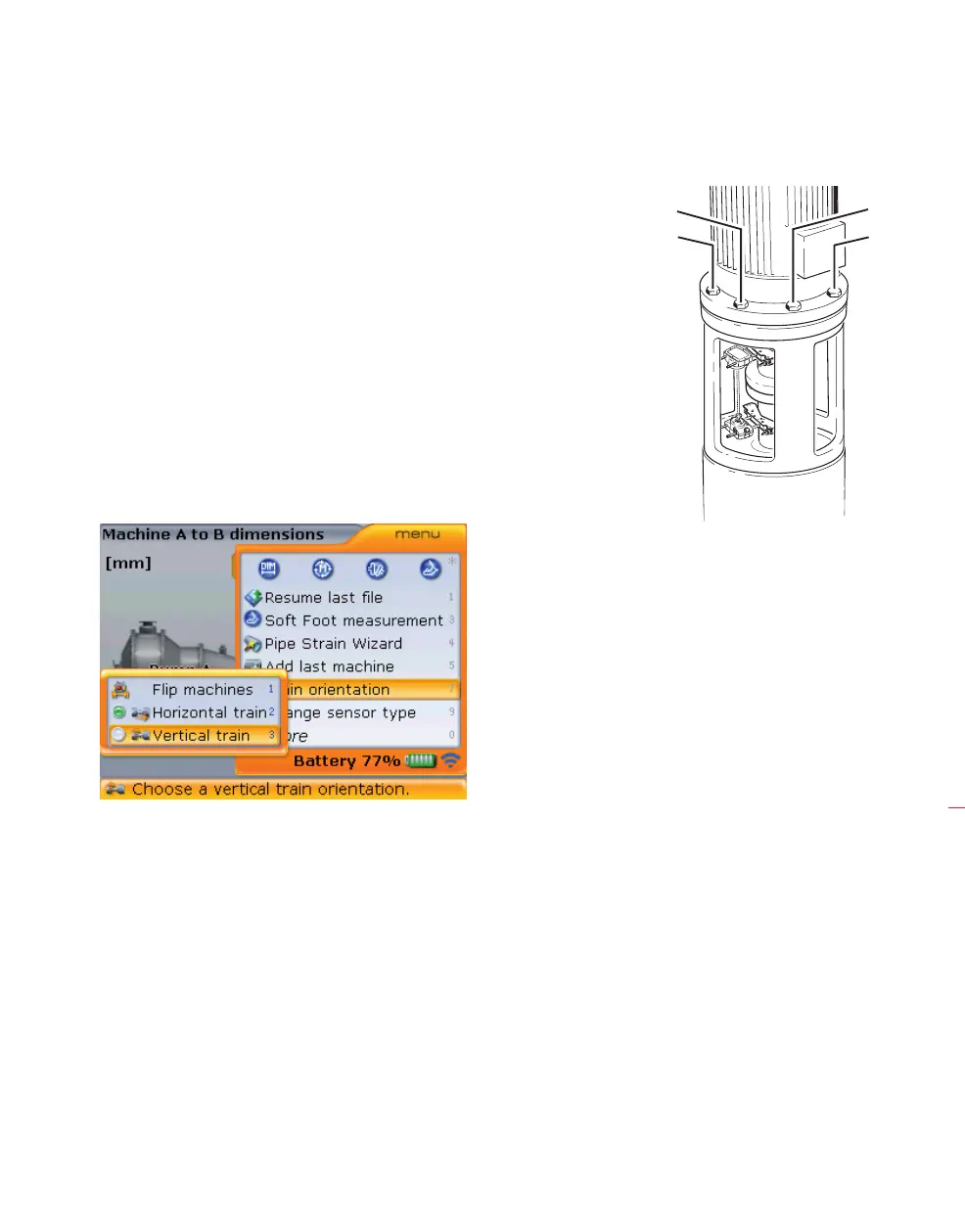
3. From the dimension screen that appears, press
q. With the context
menu displayed, use the navigation keys to highlight ‘Train orientation’ >
‘Vertical train’.
4. Confirm selected train orientation by pressing
e. A hint appears requiring the
acknowledgement of the change. Use
f/g and highlight ‘Yes’ and then
press
e to acknowledge change.
7.3.4 Editing flange configuration
A typical vertical machine train arrangement consists of machines mounted together
using a bolted flange. To configure the flange proceed as follows:
1. With MTBM highlighted press
e then use g to highlight “Change to
flange”.
9:001:30
10:300:00
Vertical flanged machines