OPTALIGN smart RS5 BT handbook
46
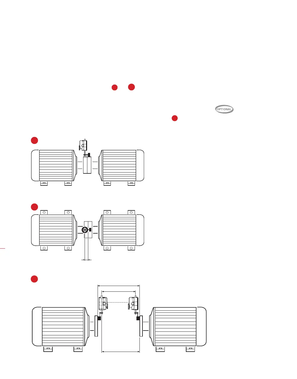
5.6.6 Entering negative dimensions
In certain circumstances or unusual machine configurations, negative dimensions may
also be entered where needed, such as coupling center-to-front foot (right machine)
when this foot is in front of the coupling center, or coupling center to sensor if the
sensor is mounted on the coupling such that the sensor distance marking is infront of
the coupling as shown in the diagrams
1a
and
1b
below.
5.6.7 Spacer shaft
If the spool piece of a spacer coupling is removed, and offset support posts used
to clear any radial obstructions, the situation illustrated in diagram
2
below could
occur.
A
B
C
Spacer removed
In the case shown, B>A
and C>A. This spacer shaft
situation is effectively
handled by OPTALIGN smart
RS5.
2
In the configuration shown,
the dimension coupling
center-to-sensor has a
negative value.
1a
1b