20
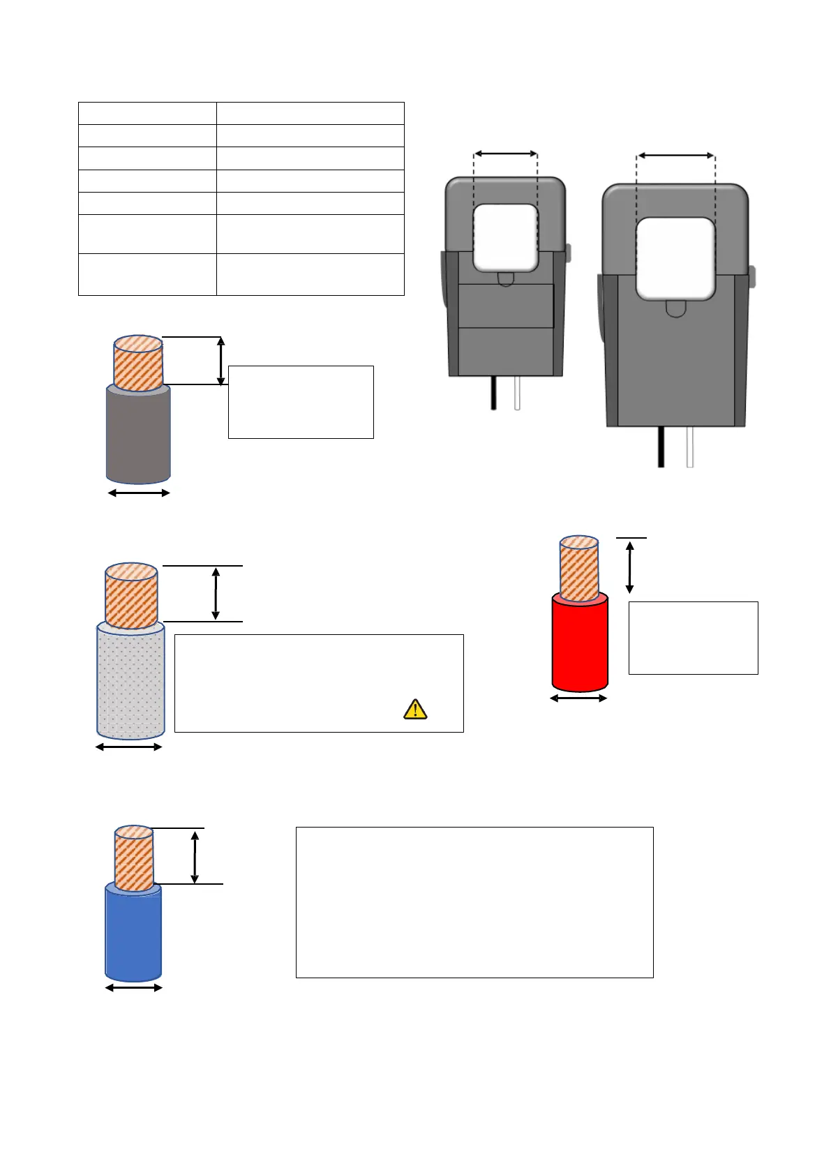
2.3.4 Wire Gauge Guide (Copper)
PV input 12 - 10 AWG
AC Inputs/Outputs 1/0 AWG - 4/0 AWG
All Sensors 20 – 24 AWG
CT Sensors 10' Wire Included
Batt Temp Sensor 6' Wire Included
RJ45 Cable 7' Included (Extendable up
to 20')
Battery input 6 – 4 AWG (Hand-Tightened
Actuation Lever)
0’~100’:12 AWG
100’~300’:10 AWG
si L1/L2/L3, Ground, & Neutral: 4/0
AWG
Gen L1/L2/L3, Ground, Neutral: 2/0 AWG
Distance Limits Will Vary Per User
(1/4in)
All Sensor Inputs
0’ – 100’: 24 AWG (Do NOT use > 20AWG)
100’ – 400’: 23 AWG CAT 6
CT Wires Can Be Extended -Extensions for Limiter
Sensors must be twisted pair (See the inverter
separate manual for details.)
(Shielded CAT6 Recommended)
(1in)
0’ – 12’: 6 AWG
12’ – 20’: 4 AWG
Regular Limiter
Sensor
Fits 4/0 AWG
300A:5A
X-Large
Limiter Sensor
Fits Metal Busbar
Grid Feed
400A: 2.0A
(1 3/8in)
(2in)