45
Danger: Damage will occur if PV VOC > 500V.
Danger: Des dommages se produiront si PV COV > 500 V.
3. Parallel strings per MPPT must be the same Voltage.
4. PV1 A/B must be the same voltage if using all two (2) strings.
5. Arrays on the same MPPT CAN face different directions.
6. Ground the panel MOUNTS/FRAMES to any ground outside the circuit via 12AWG wire.
7. IF using Y-Connectors: Running two strings in parallel, totaling 36A (self-limiting).
8.
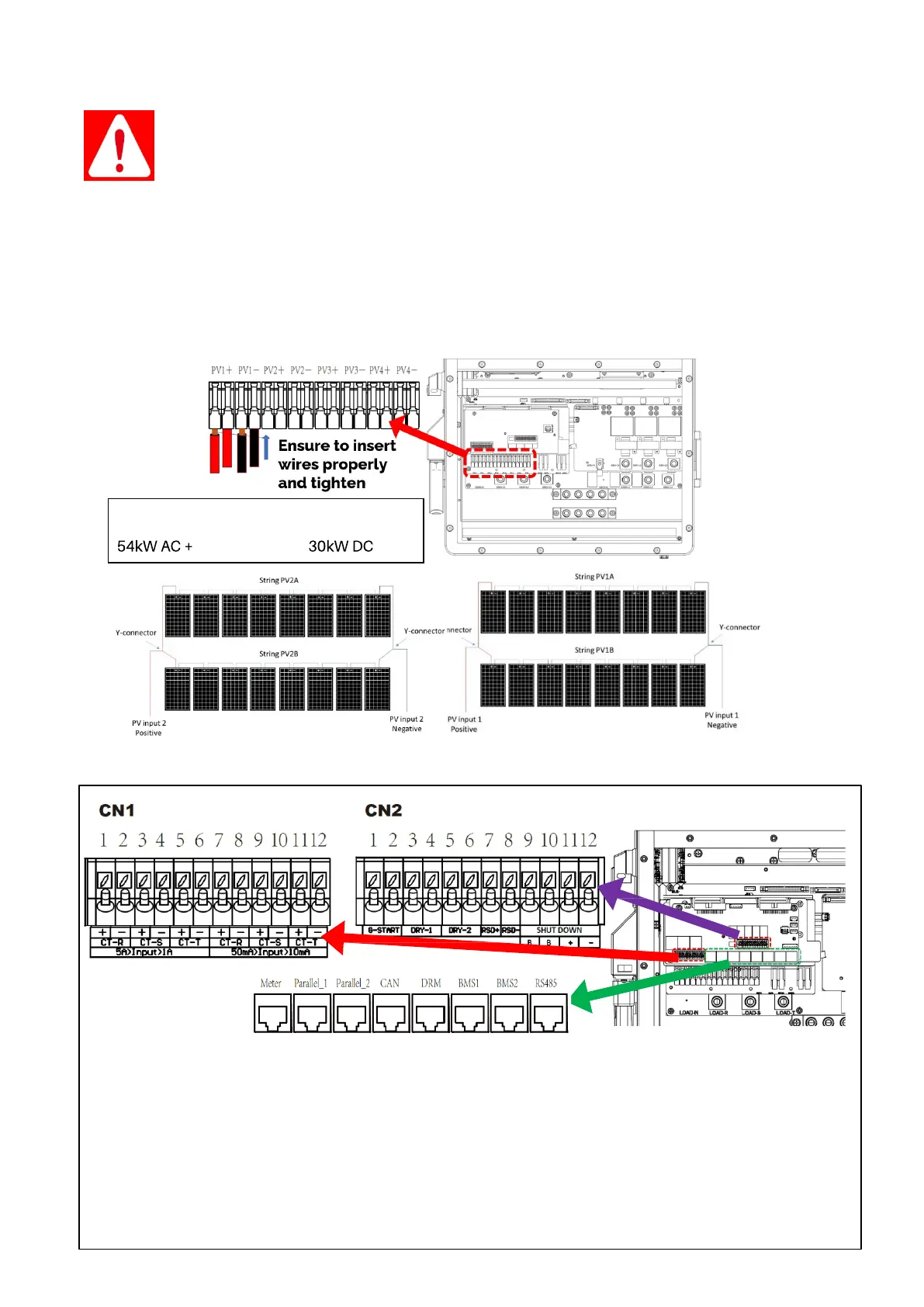
Connect the solar panel strings as indicated by the following diagram:
3.2.5.1 Sensors Integration and Accessory Placement
(1,2,7,8) CT-R: Current transformer (L1) used for Limited Power to Home mode and Peak Shaving; Polarity matters
(3,4,9,10) CT-S: Current transformer (L2) used for Limited Power to Home mode and Peak Shaving; Polarity matters
(5,6,11,12) CT-T: Current transf. (L3) used for Limited Power to Home mode and Peak Shaving; Polarity matters
(1,2) G-Start: dry contact signal for startup the generator. When the "GEN signal" is active, the open contact (GS) will close
(no voltage output).
(3,4) Dry-1 and (5,6) Dry-2: Reserved
(7,8) Optional RSD: 12V power supply for RSD transmitters; Rated for a maximum of 1.2W (100mA @12V)
(9,10) Emergency stop: Short these pins to initiate emergency stop.
Meter: For external energy meter communication
Parallel_1 & Parallel_2: Parallel communications ports 1 and 2
CAN: Reserved DRM: Reserved RS-485: RS-485 port
BMS1 & BMS2: BMS ports 1 and 2 for battery communications
Maximum combined Output (AC+DC) =
72kW
Sensor Pin Out (Local in Sol-Ark user area)