63
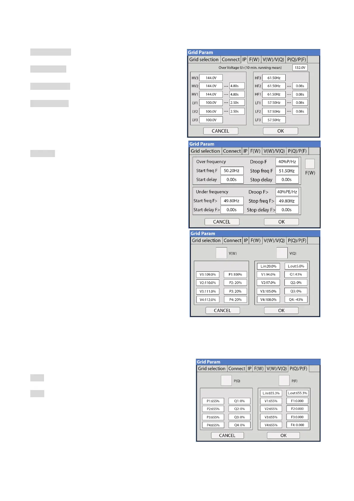
IP Tab
HV1/HV2/HV3: Overvoltage protection point
• 4.8s trip time
LV1/LV2/LV3: Undervoltage protection point
• 2.5s trip time
HF1/HF2/HF3: Over frequency protection point
• 4.8s trip time
LF1/LF2/LF3: Under frequency protection point
• 2.5s trip time
F(W) Tab
The Sol-Ark 30K-3P-208V can adjust the inverter output
power according to the grid frequency.
Droop F: The percentage of nominal power per Hertz (Hz).
Example:
Start freq F > 50.2Hz | Stop freq F < 51.5Hz
Droop F =40%P/HZ
If the grid frequency reaches 50.2Hz, the Inverter
will decrease its active power at Droop F of 40%. The
Inverter will stop decreasing output power when the
grid frequency is less than 51.5Hz.
Please follow the local grid code.
V(W) / V(Q) Tab
These functions are used to adjust the Inverter’s output
power (both active power and reactive power) when there
are changes in grid voltage.
V(W): Will be used to adjust the Inverter’s active power
according to the set grid voltage.
V(Q): Will be used to adjust the Inverter’s reactive power
according to the set grid voltage.
Example:
V2 = 110.0% | P2 = 20% When the grid voltage reaches
110% of the rated grid voltage, the Inverter will reduce its output power (active output power) to 20% rated
power
Example:
V1 = 93% | Q1 = 43% When the grid voltage reaches 93% of the rated grid voltage, the Inverter will output 43%
reactive output power.
P(Q) / P(F) Tab
P(Q): Will be used to adjust the Inverter’s reactive power
according to the set active power.
P(F): Will be used to adjust the Inverter’s PF (power factor)
according to the set active power Please follow the local
grid code.
3.2.8 Limiter Sensors (CT Sensors)
CT Sensors enable Limited Power to Home mode (meter zero)
and Peak Shaving mode. CT sensors also allow the system to calculate loads powered upstream of the Grid
Input in the “home.” We recommend CT installation if using multiple inverters or a critical loads panel.
1. CT Sensor Install Location
• Install the CT sensors on L1 and L2, and L3 upstream of everything in the home except for a Generator