43
3.2 Installation and Operation of the Inverter
3.2.1 Deciding the Site’s Backup Circuits
1. Ensure you keep the Inverter within its amperage limits.
• ON-Grid = 200A pass through (160A software limitation)
• OFF-Grid = 30kW = 83.4A Continuous | 45kVA = 125A Peak (10s)
2. Verify each load circuit by measuring typical and max Amps with a clip-on Amp meter. Amps x 120V =
Watts.
3. Install a subpanel for backup loads if there is a chance of exceeding any amperage limits while
powering the entire site off-grid; failure to do so will result in an outage and potential damage to the
Inverter.
4. If you have Arc-Fault / GFI breakers, DO NOT use a multi-circuit transfer switch.
3.2.2 Grounding Cables Installation
Danger: The system must have Ground connections and Neutral connections. Ground MUST
be bonded to
Neutral ONLY ONCE in the circuit.
Danger: Le système doit avoir des connexions à la terre et des connexions neutres. La terre
DOIT être reliée au neutre UNE SEULE FOIS dans le circuit.
See Section 2.1.1.1 for the Ground / Neutral Bars position.
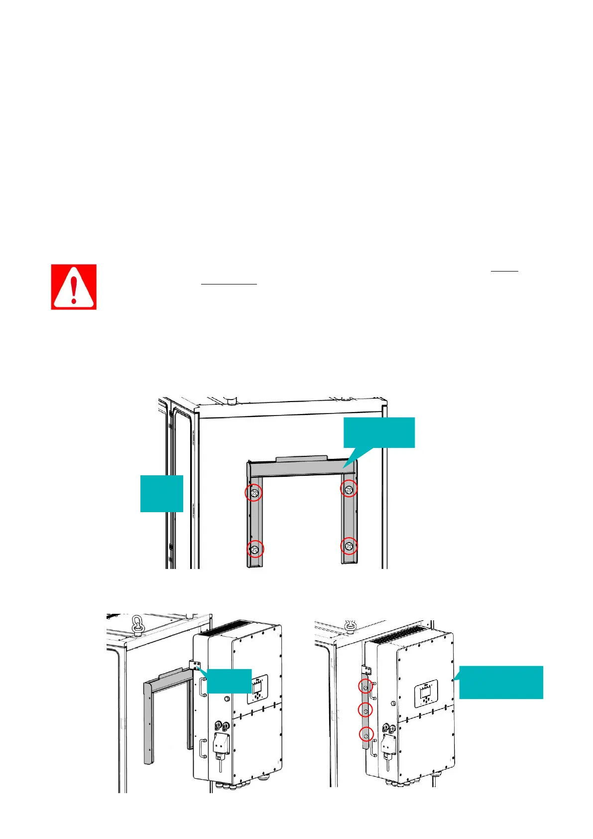
3.2.3 Mounting the Inverter on the outdoor cabinet
Please follow the steps below to mount the invert to the outdoor cabinet.
1. Aligning the four holes in the cabinet sideboard, fix the French Cleat bracket to the cabinet,
with four bolts+washers (M12x25), shown as below.
2. Install the inverter on the embedded bracket by hanging the hanger of the inverter onto the
bracket. Then fasten three bolts+washers (M4x12) on both sides of the PCS to the bracket.
door
3 bolts+washers
on the other side