46
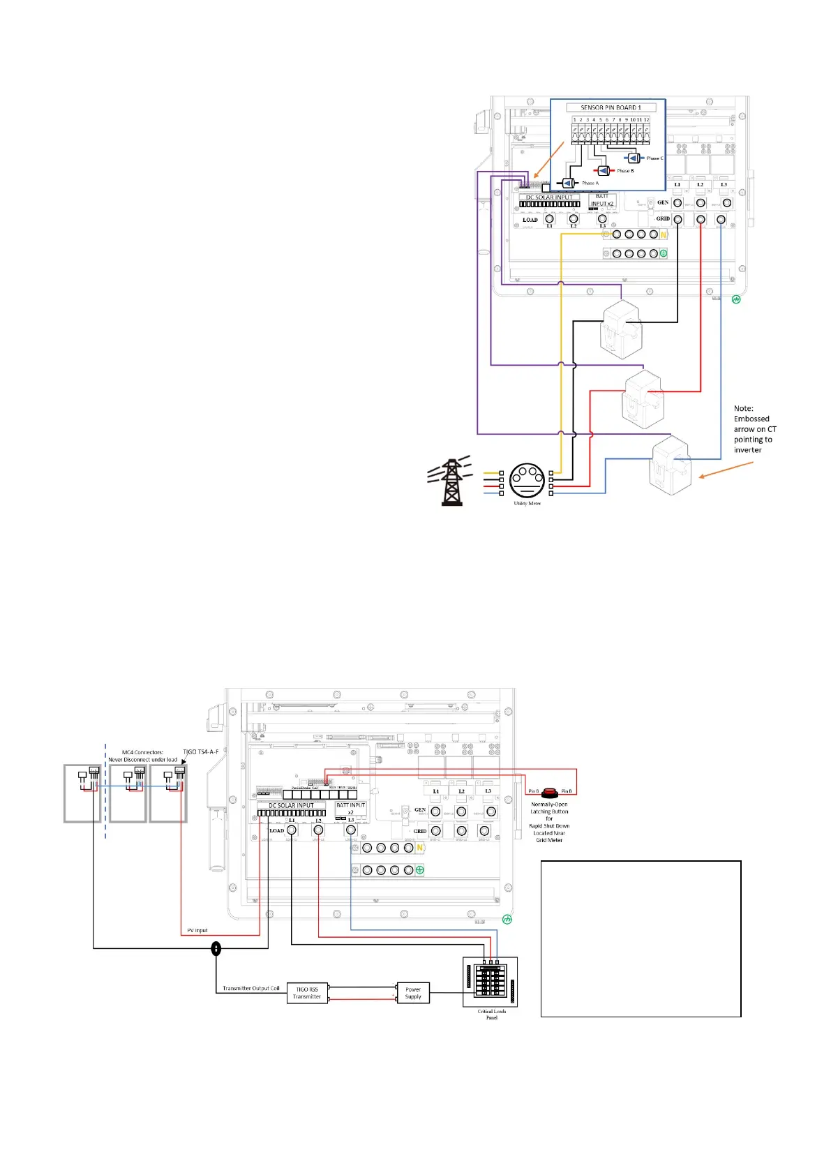
Limiter Sensors (CT Sensors) [diagram to the right]
• Install sensors on incoming electrical service
wires L1, L2, & L3 (see Diagrams Section)
• Limited Power to Home Mode (meter zero) and
Peak Shaving Modes require CT sensors
• To ensure the sensors will fit, please check the
wire size before ordering (regular CTs
accommodate up to 4/0 AWG) [Larger
available: sales@sol-ark.com]
(See the inverter separate manual for details.)
GEN Start Signal (Two-Wire)
• The signal comes from a normally open relay
that closes when the Gen Start state is active
CANbus & RS485
• To connect batteries to the Sol-Ark 30K-3P-
208V via RJ45, you need to splice the end
connecting to the 30K
• Use the middle two conductors
• RS485 is SunSpec draft 4 (will not work with
draft 3)
Wi-Fi Antenna (Dongles)
Remote monitoring and software updates require an internet connection through the Wi-Fi dongle
(ethernet available)
Emergency Stop Signal & PV Rapid Shutdown Signal
Pins 9(B) and 10 (B) in the sensor pinboard 2 use an ordinarily open & latching switch to connect the two
emergency stop pins that cut off the RSD power supply when triggered, thus stopping the inverter AC
output.
Pins 7 and 8 in the sensor pinboard 2 provide the 12V / 100mA signal power lost when the Sol-Ark shuts
down using the front button.
Wi-Fi Antenna (Dongles)
Remote monitoring and software updates require an internet connection through the Wi-Fi dongle
(ethernet available)
Emergency Stop Signal & PV Rapid Shutdown Signal
Pins 9(B) and 10 (B) in the sensor pinboard 2 use an ordinarily open & latching switch to connect the two
This diagram illustrates how to
integrate the
Tigo TS4-A-F and
the corresponding
Tigo RSS
Transmitter with the Sol-Ark
30K-3P-N.
Please refer to your RSD
manufacturer’s website for
appropriate hardware needs
and compatibility.