5G Module Series
RM500Q-GL Hardware Design
RM500Q-GL_Hardware_Design 39 / 85
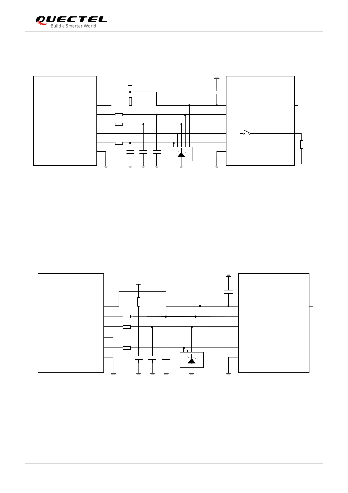
The following figure shows a reference design for (U)SIM interface with a normally open (NO) (U)SIM
card connector.
Module (U)SIM Card
Connector
USIM_DET
USIM_DATA
USIM_CLK
RST
CLK
CD1
IO
USIM_VDD
USIM_VDD
USIM_RST
VCC
GND
VPP
GND
TVS
10-20k
22R
22R
22R
33 pF
33 pF
33 pF
100 nF
0 Ω
CD2
NOTE:
All these resistors, capacitors and TVS should be close to (U)SIM card connector in PCB layout.
Figure 16: Reference Circuit for Normally Open (U)SIM Card Connector
4.1.5. (U)SIM Card Connector Without Hot-plug
If (U)SIM card hot-plug is not needed, please keep USIM_DET unconnected. A reference circuit for
(U)SIM card interface with a 6-pin (U)SIM card connector is illustrated by the following figure.
Module (U)SIM Card
Connector
USIM_DET
USIM_DATA
USIM_CLK
RST
CLK
IO
USIM_VDD
USIM_VDD
USIM_RST
VCC
GND
VPP
GND
TVS
10-20k
22R
22R
22R
33 pF
33 pF
33 pF
100 nF
NOTE:
All these resistors, capacitors and TVS should be close to (U)SIM card connector in PCB layout.
Figure 17: Reference Circuit for a 6-pin (U)SIM Card Connector
 Loading...


