5G Module Series
RM500Q-GL Hardware Design
RM500Q-GL_Hardware_Design 51 / 85
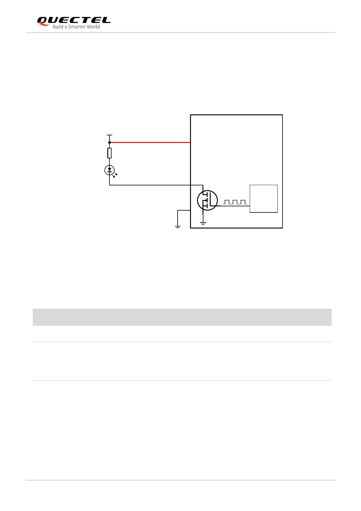
4.5.3. WWAN_LED#
WWAN_LED# is used to indicate the RF status of the module, and its sink current is up to 10 mA.
To reduce current consumption of the LED, a current-limited resistor must be placed in series with the
LED, as illustrated by the figure below. The LED is ON when the WWAN_LED# signal is at low level.
Module
WWAN_LED#
PMIC
10
VCC(Typ. 3.7V)
R1
330 Ω
LED1
2, 4
70,72,74
VCC
Figure 25: WWAN_LED# Reference Circuit
The following table shows the RF status indicated by WWAN_LED# signal.
Table 23: Network Status Indications of WWAN_LED#
4.5.4. WAKE_ON_WAN#
The WAKE_ON_WAN# is an open drain pin, which requires a pull-up resistor on the host. When a URC
returns, a one-second low level pulse signal will be outputted to wake up the host.
RF function is turned off if any of the following occurs:
⚫ The (U)SIM card is not powered.
⚫ W_DISABLE1# is at low voltage level (airplane mode enabled).
⚫ AT+CFUN=4 (RF function disabled).
 Loading...


