5G Module Series
RM500Q-GL Hardware Design
RM500Q-GL_Hardware_Design 77 / 85
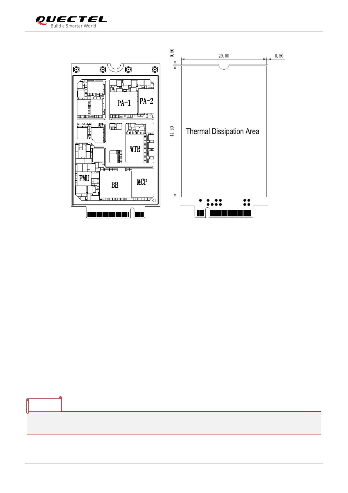
Figure 36: Thermal Dissipation Area Inside and on Bottom Side of the Module (Unit: mm)
There are other measures to enhance heat dissipation performance:
⚫ Add as many ground vias as possible on the PCB.
⚫ Maximize airflow over/around the module.
⚫ Place the module away from other heating sources.
⚫ Module mounting holes must be used to attach (ground) the device to the main PCB ground.
⚫ It is NOT recommended to apply solder mask on the main PCB where the module’s thermal
dissipation area is located.
⚫ Select appropriate material, thickness and surface for the outer housing of the application device that
integrates the module (i.e., the mechanical enclosure) to enhance thermal dissipation ability. You
may also need active cooling to dissipate heat of the module.
⚫ If possible, add a heatsink on the top of the module. A thermal pad should be used between the
heatsink and the module, and the heatsink should be designed with as many fins as possible to
increase heat dissipation area.
If a conformal coating is necessary for the module, do NOT use any coating material that may chemically
react with the PCB or shielding cover, and prevent the coating material from flowing into the module.
 Loading...


