56
GOAL of EXAMPLE: STEPS: INPUTS:
Set up a
RUDD-ELEV
curve mix on a
model that pitches down severely at
full rudder and not at all with minimal
rudder input, and pitches worse on right
rudder than left:
Point 1: 25%
Point 2: 8%
Point 3: 0%
Point 4: 10%
Point 5: 28%
ON
when SWITCH C is down.
LINK
should be
ON
if model has twin
elevator servos. Otherwise,
LINK
remains
OFF
.
(Note that point 3 is 0%. Otherwise,the
elevator would be retrimmed when the
mix is active and no rudder input is
given.)
Open an unused curve programmable
mix. (Ex: use
PROG.MIX7
since it is
already set-up for
RUDDER-ELEV
.)
for 1 second.
(If
BASIC
, again.)
C
to
PROG.MIX-
.
C
to
7 >
.
Activate the function.
C
to
MIX
. to
ON
.
Choose master and slave channels.
(Ex: do not change
MAS
or
SLV
).
already
RUDD
already
ELEV
Set
LINK
as needed. (Ex: off)
Assign SWITCH and position.
(Ex: change from
F
to
C
,
DOWN
.)
C
to
SW
. to
C
.
C
to
POSI
. to
DOWN
.
Optional: set switch to
STk-THR
to
activate mix with THROTTLE STICK.
(See above for details.)
C
to
SW
. to
STk-THR
.
C
to
POSI
.
THROTTLE STICK to desired
point.
for 1 second to set.
Optional: set switch position to
NULL
.
Makes mix active at all times. Not
compatible with
STk-THR
.
C
to
POSI
. to
NULL
.
Set desired percent at the stick points.
(Ex: listed at left.)
to page 1.
C
to
POINT-1
. to
25%
.
Repeat for points 2-5.
Close menu.
Where next? Adjust servo
END POINTs
: see p. 39.
Set up
AILEVATOR
: see p. 57.
Set up linear programmable mixes, ex:
RUDDER-to-Aux2
(twin rudder servos):see p.
53, or additional curve mix, ex:
RUDDER-AILERON
: see p. 55.
View numerous mix setups: www.radiolink.com.cn/doce
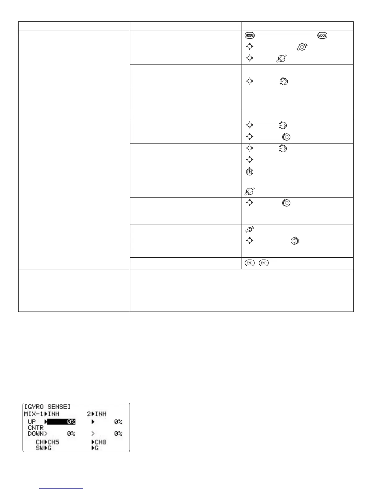
gyro mixing
Gyro operation modes:
The gyros have two operations modes: GY mode and STD mode.
•STD mode: This mode performs general proportional control operation. For instance, it controls the gyro so that
changes are countered when the attitude of the aircraft is changed by cross-wind, etc.
•GY mode: This mode performs both proportional and integrated control operation. The difference between Normal
mode and GY mode operation is that where as the Normal mode only counters changes in attitude, the GY mode
returns to the original controlled variable simultaneously with countering changes in attitude. For example, during
NQLIHHGJHÀ\LQJDLOHURQDQGHOHYDWRUPHHWLQJUXGGHULVQRUPDOO\QHFHVVDU\EXWLQWKHGYPRGHPHHWLQJUXGGHULV
performed automatically by the gyro.
Adjustability:
• Plug the gyro's sensitivity adjustment to channel 5, 7, or 8 of the receiver.
(selectable)
• Full switch assignability (SWITCH A-H)
• Each rate setting may be set from 0 to NOR100% or AVC100% gain.
NOR
: GY mode gain.
AVC
: STD mode gain
• Larger percentages indicate more gain, or gyro responsiveness.
•
MIX-1,2
: Two surfaces' sensitivity can be adjusted independently.
 Loading...