85
Adjustability:
• Plug the gyro’s sensitivity adjustment to channel 5 of the receiver. (not assignable)
•
STD
DQG$9&6+HDGLQJKROG
GY
VHWXSW\SHVDYDLODEOHWRVLPSOLI\DGMXVWPHQWVIRU$9&6+HDGLQJKROGJ\URV
• Full switch assignability or may select
Cond.
option.
•
Cond.
option provides separate gyro settings, one for each condition, automatically selected with the condition. Allows
FKDQJHVLQJDLQWRPHHWWKHVSHFL¿FQHHGVRIHDFKÀLJKWFRQGLWLRQ
• Each gyro setting may be set from 0 to +100 (
NOR
100% to
AVC
100%) gain, equating to ATV settings of -100% to +100%.
'XDOPRGHJ\URVKHDGLQJKROG$9&6DQGQRUPDODUHHDVLO\WULJJHUHGWRHDFKPRGHE\FKDQJLQJWKHJ\URVHWWLQJ¶VVLJQ
Negative settings trigger normal mode; positive settings are AVCS mode.
• Larger percentages indicate more gain, or gyro responsiveness.
• Tail wagging or shaking indicates excessive gain settings. Turn down gyro setting until wag stops.
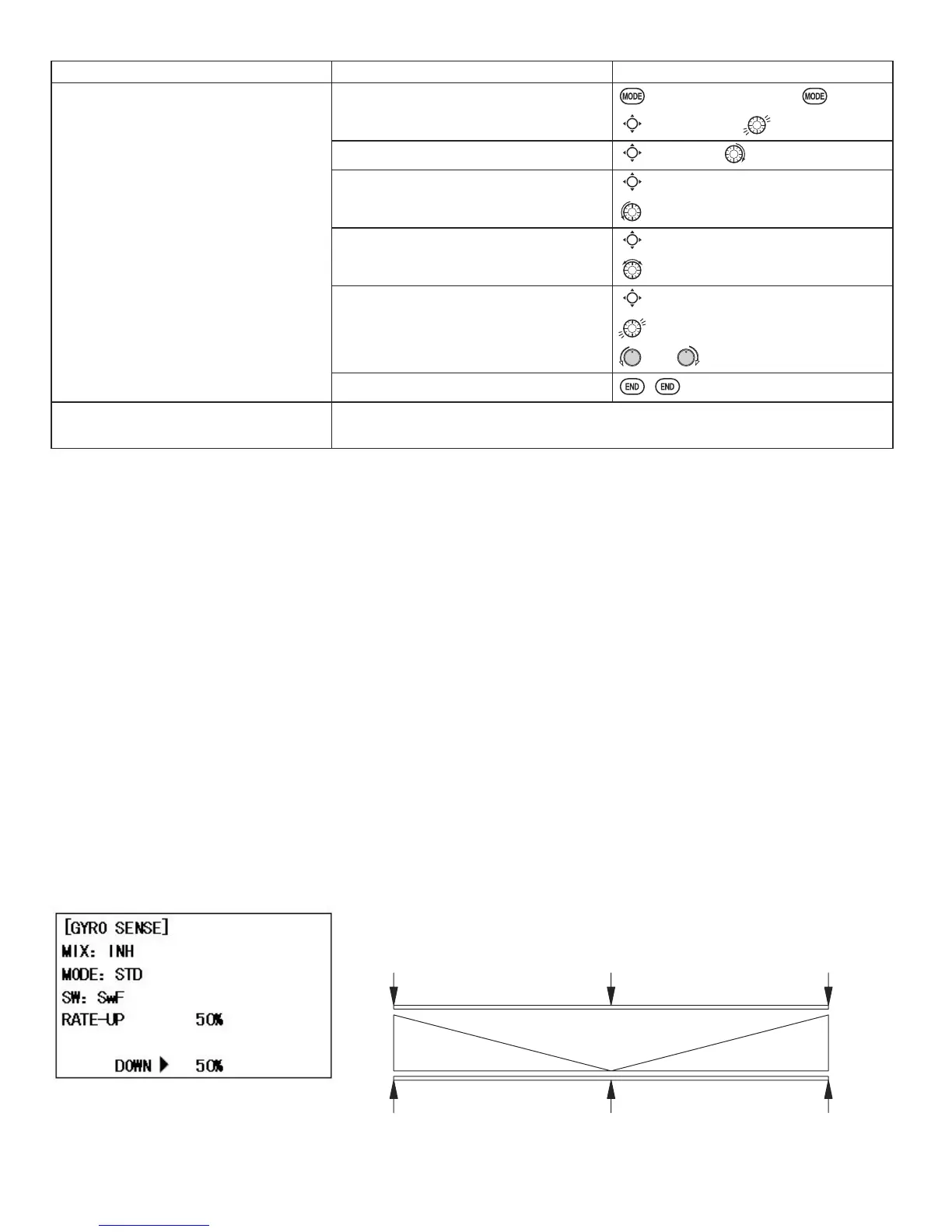
Gain Example for AVCS/Heading-hold Gyros (
GY
)
50%0% +100%
"Heading Hold Mode"
"Normal Mode"
CVA%001%0RON%001
GY
STD
*<526DQG*29(512568VLQJHOHFWURQLFVWRWDNHVRPHRIWKHFRPSOH[LW\RXWRIVHWXSVDQGÀLJKW
What is a gyro? A gyroscope is an electronic unit that senses motion and corrects for it. For example, if the wind blows
\RXUKHOLFRSWHU¶VWDLOWRWKHOHIWDJ\URZLOOVHQVHWKDWPRWLRQDQGFRQ¿UPWKDWQRLQSXWZDVJLYHQDQGZLOOFRUUHFWIRULW
How does it help in helicopter setup? A good gyro will totally eliminate the need for revo. mixing. The gyro will sense and
correct the unwanted motion for you, so you don’t have to spend time to get a complex curve operating properly.
GOAL of EXAMPLE: STEPS: INPUTS:
Set up a high pitch curve in the idle-up
1 condition.
6WRUHQHZVHWWLQJVDIWHUÀLJKW
Open the
HI/LO-PIT
function.
for 1 second.
(If
BASIC
, again.)
C
to
HI/LO-PIT
.
Select the idle-up 1 condition.
C
to
NORM
. to
IDL1
.
Set the rate. (Ex:
80%
)
C
to
HI-PIT
.
to
80%
.
Optional: change which knob adjusts
high pitch curve.
C
to
VR
.
to desired knob and direction.
Store the current dial settings prior to
selecting another model.
C
to
HI-PIT
.
for one second to store.
or VR(E) to center.
Close.
Where next?
PIT-CURVE
: see p. 80.
HOV-PIT
: see p. 83.
 Loading...