20
20
Installation
ESP-Me Advanced User Manual
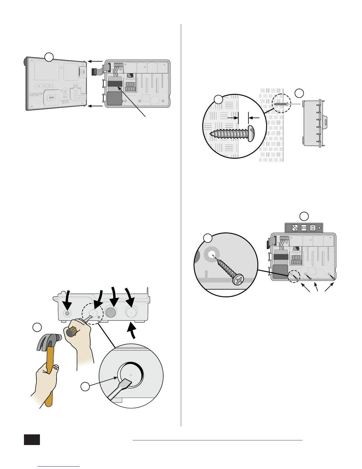
3. Remove the front panel by gently pulling the panel
upward and sliding the bottom corner pin out of the
lower pin-hole.
1 2 3 4
VT = VALVE TEST
VT MV COM
24 VAC
GND
SENS
VT MV COM 5 6 7 11 12 13 17 18 19
1 2 3 4 8 9 10 14 15 16 20 21 22
CONNECT
120 VAC
* TRANSFORMER
3.
Remove Knock-outs
The ESP-Me controller cabinet has four “knock-outs”
available for connecting conduit and routing eld wires.
Three knock-outs are located on the underside of the
cabinet and one is located on the back.
Tools Required:
Flat-head screwdriver
Hammer
If a knockout needs to be removed:
1. Place the blade of the screwdriver into the groove
around the knockout and tap it with a hammer.
2. Punch a hole through the material in two or more
places and twist to remove.
2.
1.
OPTIONAL
Mount Controller
1. Drive a mounting screw for the top anchor into the wall.
Leave an 1/8 inch gap between the screw head and the
wall surface. (Use wall anchors if necessary.)
2. Locate the keyhole slot on back of the controller unit
and hang the unit securely on the mounting screw.
1/8 IN.
1.
2.
3. Ensure the unit is level.
4. Drive three additional mounting screws through the
open holes inside the controller and into the wall. Verify
that the unit is fastened securely to the wall.
1 2 3 4
VT = VALVE TEST
VT MV COM
24 VAC
GND
SENS
VT MV COM 5 6 7 11 12 13 17 18 19
1 2 3 4 8 9 10 14 15 16 20 21 22
CONNECT
120 VAC
4.
3.