Raisecom
ISCOM5508 (B) Hardware Description
Raisecom Technology Co., Ltd.
Turn off the power switch or disconnect the power connection before installing or
removing the power cable.
Ensure that the label on the power cable is correct before connecting the power
cable.
Use the power cable compliant with required specifications.
2.5.2 Panel and slots
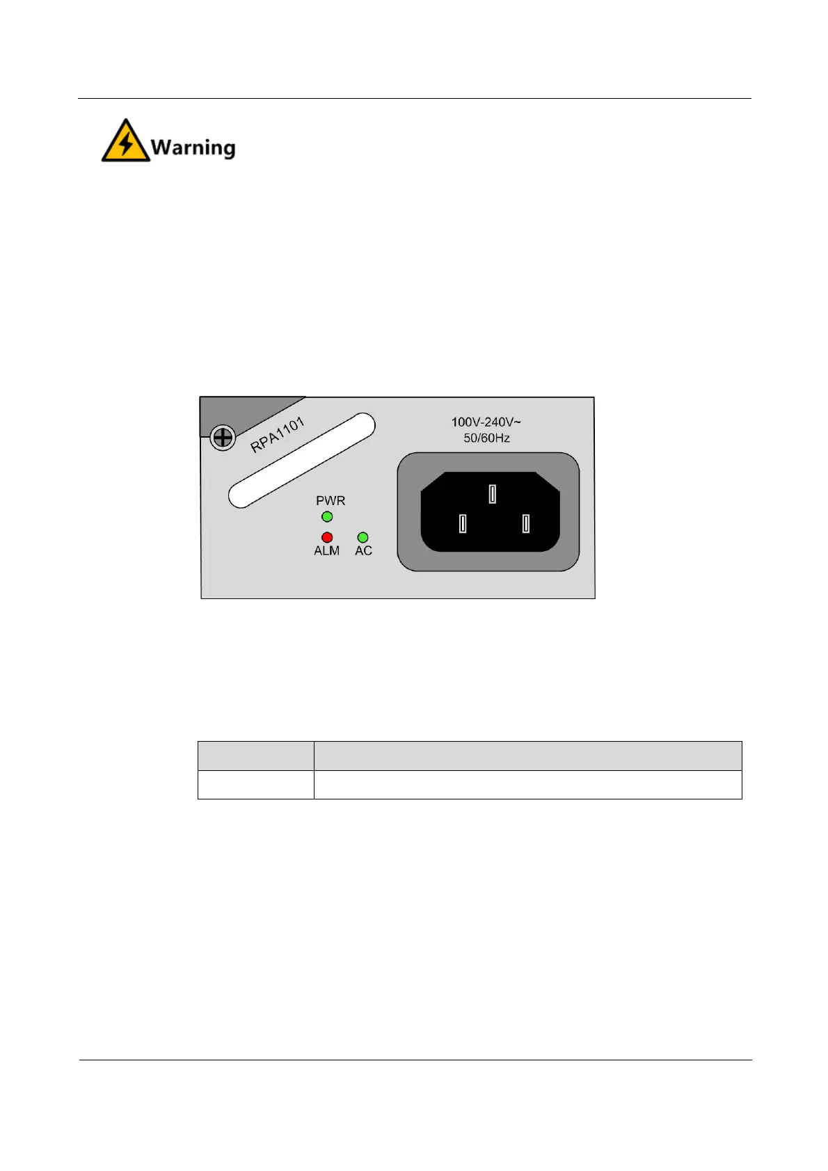
The RPA1101 power module can be inserted into slot 4 or slot 5.
Figure 2-10 shows the panel of the RPA1101 power module.
Figure 2-10 Panel of the RPA1101 power module
2.5.3 Interfaces
There is 1 interface on the RPA1101 power module.
Table 2-16 lists the interface on the RPA1101 power module.
Table 2-16 Interface on the RPA1101 power module
AC power interface/receptacle socket
2.5.4 LEDs
There are 3 LEDs on the RPA1101 power module.
Table 2-17 lists LEDs on the RPA1101 power module.