Raisecom
ISCOM5508 (B) Hardware Description
Raisecom Technology Co., Ltd.
3.3.3 Technical specifications
PIN definitions
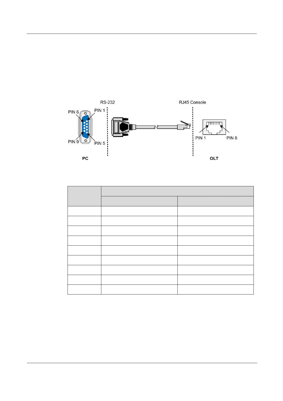
The configuration cable is used to connect the Console interface of the ISCOM5508 and the
RS-232 serial interface of the maintenance console.
0 shows PINs on both connectors of the ISCOM5508.
PINs on both connectors of the ISCOM5508
Table 3-6 lists PIN definitions of the Console interface and RJ45 interface
Table 3-6 PIN definitions of the Console interface and RJ45 interface
Maintenance console (DB9)
Wiring scheme
Figure 3-8 shows wiring between the Console interface and the RS-232 serial interface.