Raisecom
ISCOM5508 (B) Hardware Description
Raisecom Technology Co., Ltd.
2.6.2 Panel and slots
The RPD1101 power module can be inserted into slot 4 or slot 5.
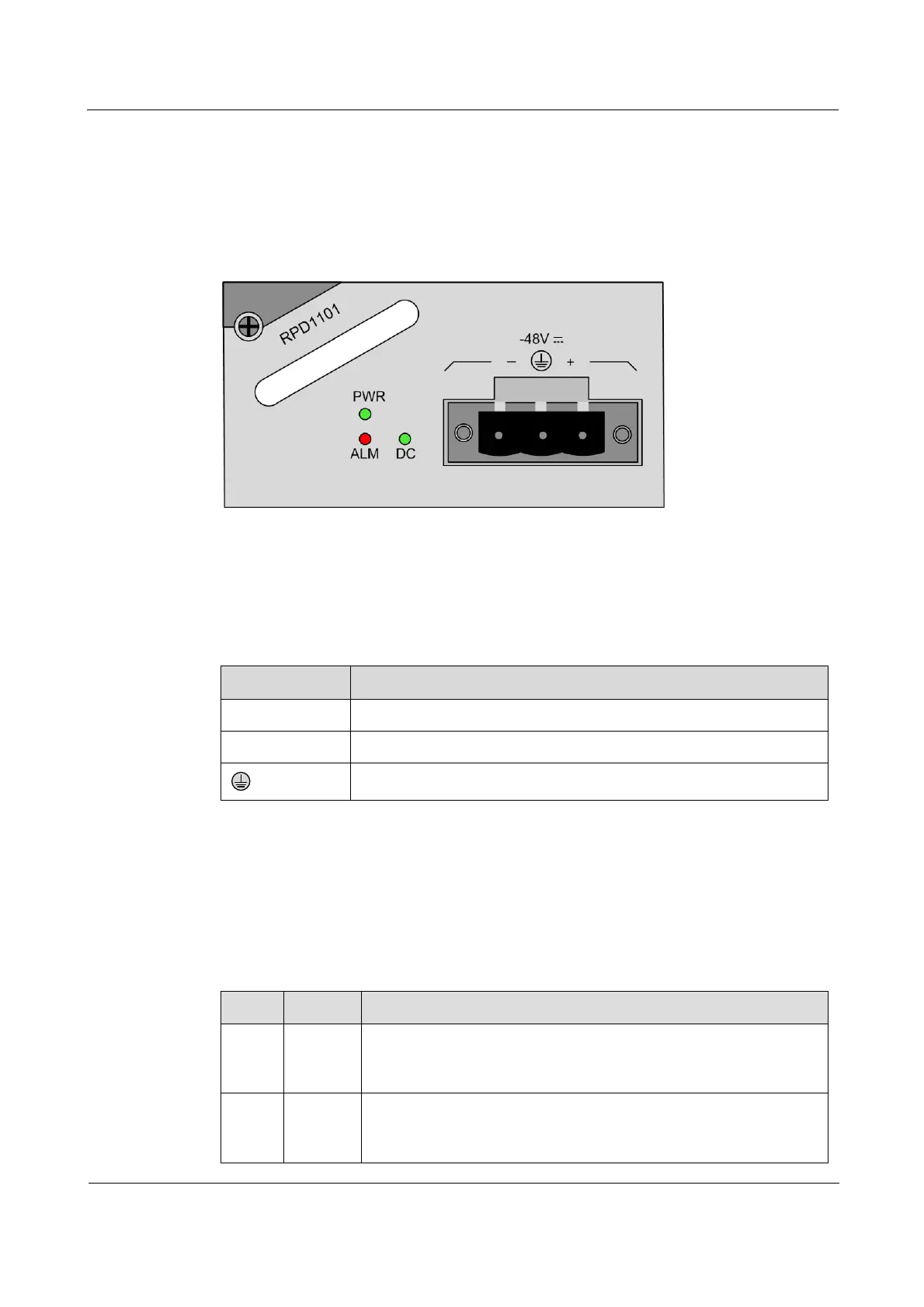
Figure 2-11 shows the panel of the RPD1101 power module.
Figure 2-11 Panel of the RPD1101 power module
2.6.3 Interfaces
There is 1 interface on the RPD1101 power module.
Table 2-19 lists the interface on the RPD1101 power module.
Table 2-19 Interface on the RPD1101 power module
2.6.4 LEDs
There are 3 LEDs on the RPD1101 power module.
Table 2-20 lists LEDs on the RPD1101 power module.
Table 2-20 LEDs on the RPD1101 power module
Power LED
Green: the power supply is working properly.
Off: the power supply is working improperly.
Power input LED
Green: the input power is working properly.
Off: the device is powered off or powered on improperly.