Raisecom
ISCOM5508 (B) Hardware Description
Raisecom Technology Co., Ltd.
Figures
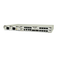
Figure 1-1 Appearance of the ISCOM5508 chassis ............................................................................................... 2
Figure 1-2 Distribution of slots on the ISCOM5508 .............................................................................................. 2
Figure 2-1 Appearance of the MCC (EPSC) .......................................................................................................... 5
Figure 2-2 Appearance of the EP4B sub-card ........................................................................................................ 5
Figure 2-3 Appearance of the GE4B sub-card ....................................................................................................... 6
Figure 2-4 Appearance of the power module ......................................................................................................... 6
Figure 2-5 Appearance of the fan module .............................................................................................................. 6
Figure 2-6 Hardware information label on the ISCOM5508 ................................................................................. 7
Figure 2-7 Panel of the EPSC card ......................................................................................................................... 8
Figure 2-8 Panel of the EP4B sub-card ................................................................................................................ 11
Figure 2-9 Panel of the GE4B sub-card ............................................................................................................... 13
Figure 2-10 Panel of the RPA1101 power module ............................................................................................... 15
Figure 2-11 Panel of the RPD1101 power module ............................................................................................... 17
Figure 2-12 Panel of the FANS306 module ......................................................................................................... 19
Figure 3-1 LC/PC fiber connector ........................................................................................................................ 21
Figure 3-2 SC/PC fiber connector ........................................................................................................................ 22
Figure 3-3 Ethernet cable ..................................................................................................................................... 23
Figure 3-4 Wiring of the straight-through cable wiring ....................................................................................... 24
Figure 3-5 Wiring of the 100 Mbit/s crossover cable ........................................................................................... 25
Figure 3-6 Wiring of the 1000 Mbit/s crossover cable ......................................................................................... 25
Figure 3-7 Configuration cable ............................................................................................................................ 26
Figure 3-8 Wiring between the Console interface and the RS-232 serial interface .............................................. 28
Figure 3-9 DC power cable .................................................................................................................................. 29
Figure 3-10 European standard AC power cable .................................................................................................. 30
Figure 3-11 American standard AC power cable .................................................................................................. 30
Figure 3-12 Grounding cable ............................................................................................................................... 31