Page 12 WES
3
Installation and Operations Manual V2.0 Ramtech Electronics Limited 2020
Ensure that any WES
3
device to be paired is turned on and has an
amberashingLED.Thisindicatestheunitisreadytopair.Unitscan
be numbered any four digit number from 0001 to 9999 in accordance
with your site plan. Numbering allows messages and alerts during
operationtobereferencedtoaspecicunitlocationonsite,usingthe
project site plan.
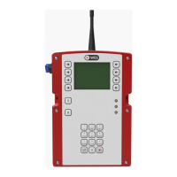
FromtheUnitNumberingscreen,usethenumerickeypadand/orthe+
and-buttonstoselectthedesirednumberforyourrstunit(example
below shows that we’ve selected the number 3).
Press and hold ‘A’ on both units. The amber LEDs will illuminate
followed by the green LEDs on both units to indicate that the units
have been successfully paired and a site group created. Release the
‘A’ buttons.
After successfully numbering a unit, change the number displayed on
the CONNECT unit and repeat the process above for all required units.
Note that the Polling feature of WES
3
can perfom an automatic integrity
testoftherst128WES
3
units added to a network. Additonal units
can be added to the network, but will be excluded in the integrity test.
If the red LED illuminates, pairing has failed. Ensure the unit to be
numbered is turned on, and repeat the Unit Numbering process,
ensuring you haven’t used the same number twice.
4. Add units to an existing group
Repeat steps 2 and 3 above.
5. Position units on site
Once activated and paired, WES
3
units can be installed on site. Ensure
any applicable local legislation or Standards regarding locating units on
site are adhered to, such as BS 5839-1 in the UK.
Wherever possible, avoid positioning the unit directly adjacent to metal
frames, metal surfaces, electric cables and similar equipment that may
interfere with the signal strength. WES units should only be installed
indoors.
6. Securely x the units in place
Each WES
3
unitmustbesecurelyxedinplacetoensurecorrect
operation. The tamper switch on the rear of the unit must be in contact
with the wall or ceiling.
• Detector units are ceiling mounted and intended for indoor use
only. Installation of detectors may involve working at height or on
elevated platforms. Ensure a risk assessment has been carried
out and all reasonable safety precautions are in place before
commencing work.
• Callpointsmustbesecurelyxed,withtheantennaupright,
to a robust vertical surface such as a wall or trolley. Where the
existingsurfaceisunsuitablefordirectxing,theCallPointcan
be mounted to backing board or pattressing such as plywood or
similar sheet material.
Each unit should be securely mounted using its two integrated
mounting points with M4 x 50mm pan head screws and wall plugs or
otherxingsselectedfortheparticularwallorceilingtype.Ensurethat
allxingpointsaresecureandthatthebacktamperisfullydepressed.
7. Test the system
After installation of the units, it is essential to perform a system alarm
testtoconrmproperoperationofthesystem.Itisalsobestpractice
to conduct a full system test on a weekly basis. This test should also
beperformedfollowinganysignicantchangetothesiteenvironment
(new structure, wall or construction equipment installed) that may affect
the network signal.
The System Test is started from the Tests selection via the CONNECT
Main Menu:
Basic System Operation