EasyManuals Logo

R&S FSH series User Manual

R&S FSH series
130 pages
To Next Page IconTo Next Page
To Previous Page IconTo Previous Page
Page #28 background imageLoading...
Page #28 background image
26
PD 1309.6269.62-02
2
Putting into Operation
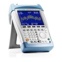
2.1 Front view
1 RF-input N-connector
2 Connector for headphones
3 BNC-connector for:
External trigger/external reference input/IF
output (IF-Out)/Video Out or BIAS port
AUX connection for additional accessories
4 LAN and USB interface
5 Softkey caption
6 Softkeys
7 Function keys
8 (Alpha-)numeric keypad
9 Kensington lock
10 DC connection for supply from the external AC
power supply
11 On/Off button
12 Entry keys
13 Unit keys
14 Cursor keys
15 Preset key
16 Rotary knob
17 Screenshot key
18 Setup key
19 Display
20 SD card slot
21 Generator output N-connector
22 Connector for power sensor
GalaxyE_v1-10_3.indd 26GalaxyE_v1-10_3.indd 26 08.04.2009 15:21:3808.04.2009 15:21:38

Table of Contents

Questions and Answers:

Question and Answer IconNeed help?

Do you have a question about the R&S FSH series and is the answer not in the manual?

R&S FSH series Specifications

General IconGeneral
Input Impedance50 Ω
Display640 x 480 pixels
Tracking generatorOptional
InterfacesUSB, LAN
Third Order Intercept (TOI)+15 dBm typical
Input VSWR≤1.5:1 (typical)
Input ConnectorN (f)
Power Supply100 V to 240 V
Frequency range9 kHz to 3.6/8/13.6/20 GHz
Battery lifeApprox. 4 hours (standard battery)

Related product manuals