10 | Gas connection for gas units
80.06.083_iCombiPro-iCombiClassic_IM_en-US 81 / 100
n
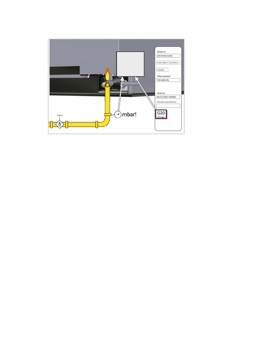
The gas type and the dynamic connection pressure set in the unit must
match the specifications on the type plate.
n
If the line pressure deviates from the connection flow pressure of the unit,
contact your gas supply company.
n
Observe the regulations of the local gas supply company.
Requirements for gas supply and gas lines
n
The flue gas analysis may only be carried out by a technician authorized by
the manufacturer. The flue gas analysis must be carried out before commis-
sioning.
n
The gas connection may only be carried out by a locally approved gas in-
staller.
n
The gas connection line must be designed for the nominal heat load speci-
fied on the type plate.
n
The gas supply and gas distribution in the unit must be checked for leaks us-
ing a suitable gas leak detector.
n
The cross-section of the gas line must be designed for the maximum con-
nected power of all consumers, at least ¾ inch for a single unit, line size
must increase with increased number of units on same line.
n
A gas shut-off valve must be installed upstream of each unit.
n
All on-site connection parts must be tested in accordance with DIN-DVGW
(the local regulations).
The hose for the gas connection must not be longer than 2.0m [78 3/4
inch].
n
The gas line can be connected to a gas socket.
n
A connection with the appropriate counterpart to the ¾inch internal thread
(RP thread) is required to connect the gas line.
n
The unit must be secured against slipping (safety cable restraint)