14 | City Series CV40E-12
owner's information
Proame II Remote Control Operating Instructions
The Proame 2 Transmitter controls the following hearth appliance
functions:
1. Main burner on/o.
2. Main burner ame modulation (6 levels).
3. Choice of standing or intermittent pilot (CPI/IPI) (non power vent
only).
4. Thermostat and smart thermostat functions.
5. Accent light modulation (6 levels).
6. Split ow valve (not available).
7. On/O relay.
8. Comfort fan speed modulation (6 levels) (not available).
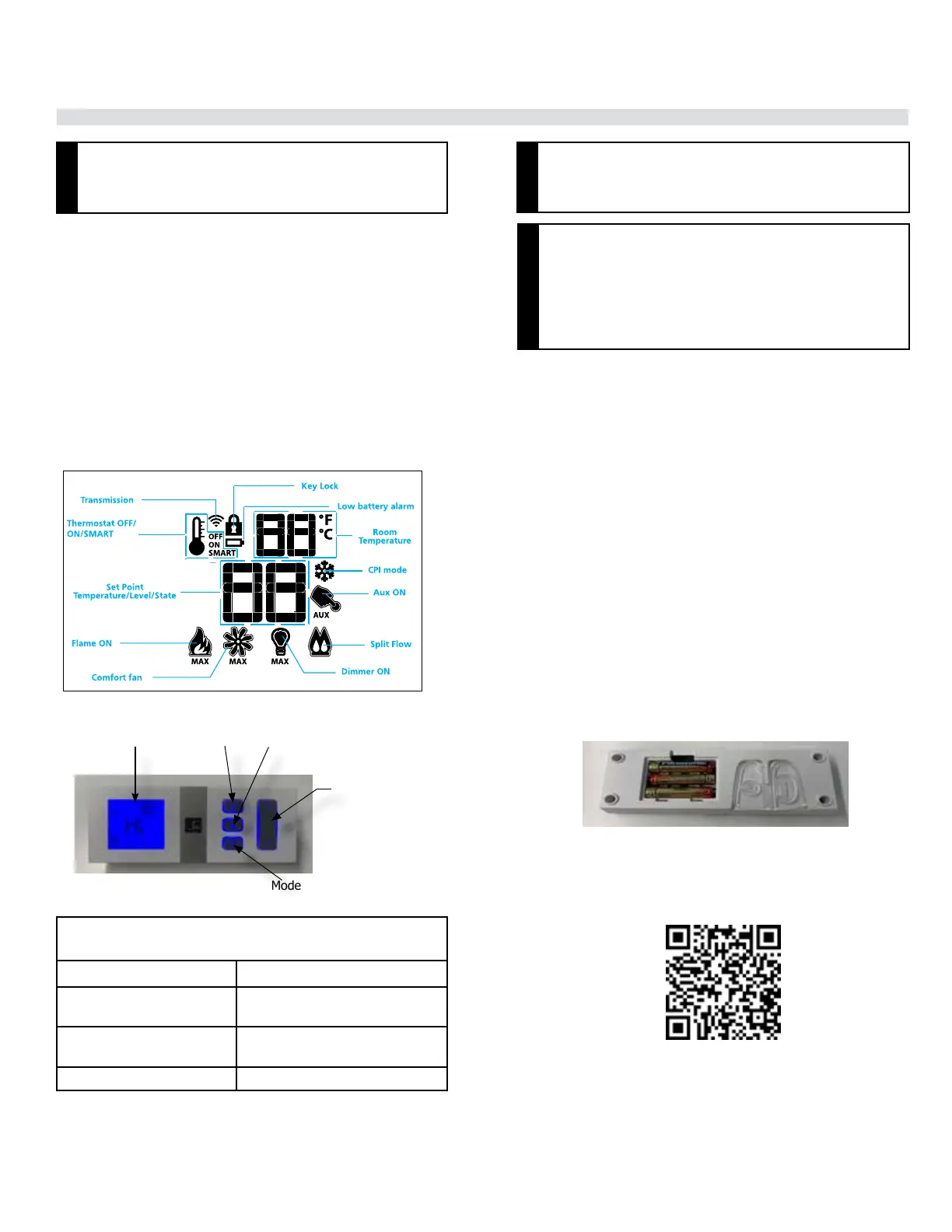
Figure 1: Transmitter LCD Display
TECHNICAL DATA
REMOTE CONTROL
Supply voltage 4.5V (three 1.5V AAA batteries)
Ambient temperature rat-
ings
0 - 50
o
C (32 - 122
o
F)
Typical operative distance
in free air
12 m (39 ft)
Radio frequency 315 MHZ (FCC version)
Non-Power Vent Model: Install the 4 AA batteries during power out-
ages to run the main burner. However, the lights will not operate.
Power Vent Model: This appliance will not operate if 120 volt power
is lost within the home.
This appliance requires coding/pairing of the remote control and IFC
(Integrated Fireplace Control). See instructions in this manual.
Figure 3: Battery compartment
Pairing the remote control to remote receiver/
battery holder (if required)
Power the receiver and press the PRG button located on its top right
corner - see the receiver instruction marked (*). The receiver will beep
three times when ready to synchronize with a transmitter. Install three
AAA batteries in the battery bay, at the base of the transmitter (g. 3).
Press the ON button. The receiver's command is accepted and sets to
the particular code of that transmitter. The system is now initialized.
(*) The receiver may be independent or integral to the IFC hearth appli-
ance control module. The receiver instruction may not be independent
when part of the IFC.
Figure 2: Proame Transmitter
The Proame Transmitter uses a streamlined design with a simple button
layout and informative LCD display (g. 1). A mode key scrolls between
the features and a thermostat key is used to turn on/o or scroll through
thermostat functions (g. 1 & 2). There is also a key lock feature (g. 2).
NOTES
The Proame Transmitter 2 is an integrated part of the Proame
2 System, which consists of these elements:
• Proame 2 Transmitter, in conjunction with
• Integrated Fireplaces Control (Proame 2 IFC)
WARNING
The transmitter and IFC are radio frequency devices.
On/o key
Thermostat Key
Up/Down Arrow Key
Mode Key
Back lit LCD display
ATTENTION
• Turn OFF the main gas supply of the appliance
prior to installation or maintenance of the IFC, and
removing or reinserting the batteries.
• In case of remote control malfunction, turn o the
IFC device using the ON/OFF main switch.
• For installation / maintenance, switch o the IFC
device removing main power supply plug.