56 | City Series CV40E-12
installation
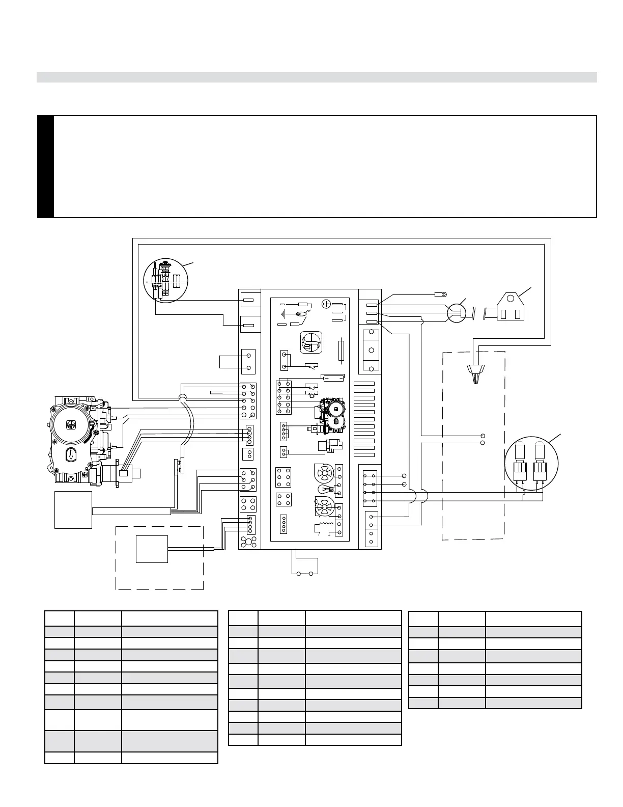
Non-PV Wiring Diagram
Item Part # Description
1 911-280 Pilot Assembly NG
911-280 Pilot Assembly LP
W840470 Pilot Gasket (not shown)
2 911-110 Spark Electrode
3 911-111 Flame Sensor Electrode
4 911-311 PFII IFC Board
5 N/A Green to Ground
6 911-344 Power Harness w/Aux
Connector
7 911-253-
ASM
Main Line
8 911-272 Variable Lights
Item Part # Description
9 N/A Electrical Shielding Box
10 N/A PV Switch
11 N/A Load
12 N/A Diagnostic Interface
13 N/A Combustion Blower
14 N/A Lamp
15 N/A User Interface
16 N/A Comfort Fan
17 N/A Split Flow
18 N/A Motor
Item Part # Description
19 911-182 Fuse
20 911-193 Connector w/Jumper
21 911-181 Battery Connection
22 911-337/P Battery Holder
23 911-188 SIT Gas Valve NG
23 911-189 SIT Gas Valve LP
24 946-799 SIT WIFI Dongle Kit
While the burner does not require a 120 V A.C. power supply, it is highly recommended as a primary power source. Batteries (4 AA) should be used as a
secondary power source only.
CAUTION
• Label all wires prior to disconnection when servicing controls. Wiring errors can cause improper and dangerous
operation.
• Ensure that the wires do not touch any hot surfaces and are away from sharp edges.
• This appliance is equipped with a three-prong (grounding) plug for protection against shock hazard and should be
plugged directly into a properly grounded three-prong receptacle. Do not cut or remove the grounding prong from
the plug.
• Electrical power must be brought to the appliance by a licensed electrician. Do not cut the ground terminal o
under any circumstances.
EV P/M
EV GND
APS
IPI/CPI
BAT -/+
ON/OFF
X11
X10
X12 X13
X2
X3
X4
X5
X6
X7
X8
X9
X0A
X1
N
L
AUX
N
L
EV P/M
EV GND
APS
IPI/CPI
BAT -/+
ON/OFF
X11
X10
X12 X13
X2
X3
X4
X5
X6
X7
X8
X9
X0A
X1
N
L
AUX
N
L
LOAD
BLACK
BROWN
YELLOW
ORANGE
GREEN
ORANGE
YELLOW/GREEN
BLACK
RED
YELLOW
YELLOW
BLACK
BLACK
GREEN
BLUE
BLACK
GREEN TO GROUND
BLUE
RED
WHITE
BLACK
BLACK
BLACK
WHITE
BLACK
BROWN
YELLOW
ORANGE
GREEN
ORANGE
YELLOW/GREEN
YELLOW
YELLOW
BLACK
BLACK
GREEN
BLUE
BLACK
GREEN TO GROUND
BLUE
RED
WHITE
BLACK
WHITE
BLACK
BLUE
RED
WHITE
BLACK
RED
BLUE
BLUE (NO)
RED (COM)
COPPER LINE TO GROUND
COPPER LINE TO GROUND
BLACK
BLACK
PRESSURE SWITCH
BLACK
RED
BLACK
BLACK
WHITE
10
9
11
8
7
6
5
4
19
18
17
15
16
14
13
12
20
3
2
1
23
21
22
24
15
29
25
26
28
27
3
2
1
4
5
6
7
24
14
12
11
10
9
8
13
21
19
18
16
17
20
22
23
NON PV