City Series CV40E-12 | 63
installation
IMPORTANT INSTALLATION NOTE:
The battery holder must be placed inside the supplied (low voltage) junction type wall box and installed into
the wall only.
DO NOT INSTALL WITHIN THE CONFINES OF THE FIREPLACE
SWITCH MUST BE ACCESSIBLE
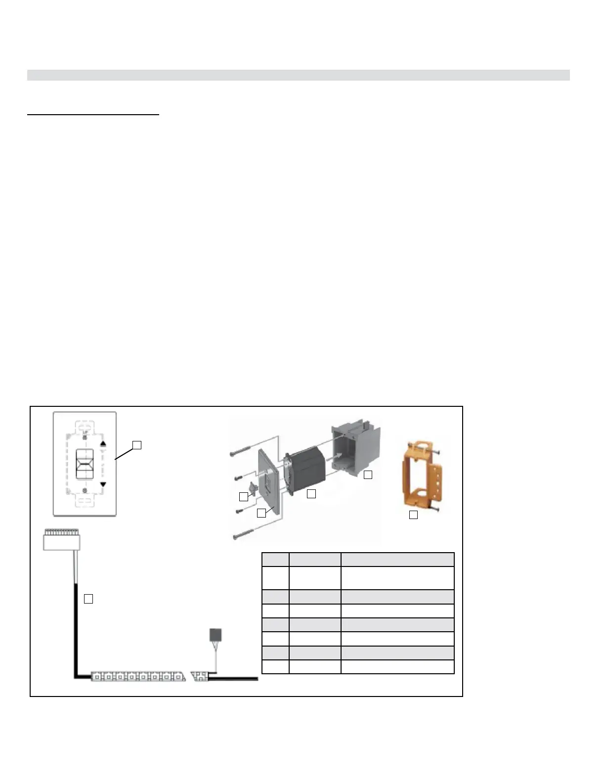
Battery Holder Installation
1. Install the low voltage junction box to the framing, at desired location within 11-1/2 ft. from replace.
2. Feed the 6 pin connector wiring harness through the opening at back of junction box. The wiring harness
is located on the right hand side and must be installed prior to nishing.
3. Connect the 6 pin connector to the back of the Battery Holder.
4. Install the Battery Holder in the Low Voltage Junction box.
5. Insert the 4 AA type batteries in the battery compartment with the correct polarity.
6. Place the slider into the cover plate.
7. Put the Battery Holder switch in the “OFF” position, to allow correct lineup for slider switch.
8. Make sure the Battery Holder and cover plate words “ON” and “UP” are on the same side.
9. Align the slider with the switch on the Battery Holder and couple the switch into the slider.
10. Align the screw holes.
11. Using the two (2) screws provided secure the cover plate to the Battery Holder.
12. For coding instructions, see full details in this manual.
Proame Battery Holder
Wall Mount On / O Switch and Battery Holder Installation
Required for all installations
ON
REMOTE
OFF
6
5
Item Part No. Description
1 N/A Slider Switch (included with
wall plate)
2 911-335 Wall Plate - White
911-343 Wall Plate - Black
3 911-337/P Battery Holder
4 N/A J-Box
5 910-369 Low Voltage Junction Box
6 911-181 Battery Holder Wire Harness
2