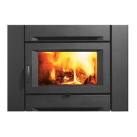
26 | City Series CV40E-12
installer's information
Installation Checklist
1. Locate appliance. Refer to the following
sections:
a) Locating Your Fireplace
b) Clearances
c) Combustible Mantel Clearances
d) Framing & Finishing
e) Venting. See the "Venting Introduction" to
"Venting Arrangements" sections.
2. Assemble Standos. Refer to the "Unit Assembly
Prior to Installation" section. (NOTE: must be
done before installing unit into replace.)
3. Install vent. See the "Horizontal Installations"
to "Installation Procedures" sections.
4. Wire 120 volt AC power to the supplied
receptacle box located on lower left hand side of
appliance. The Duplex receptacle and receptacle
cover are also included and will be located in
the manual package. Note : This heater does
not require 120 volt AC supply for operation
of the burner but is highly recommended as a
primary power source to eliminate the need for
4 AA batteries. Batteries should only be used
as a secondary power source when power is
lost within the home. 120 Volt AC power is also
required for operation of the lights.
5. Install junction box supplied with appliance.
Install remote battery box inside of junction box.
Hook battery box to wire marked receiver. This
will enable operation of the burner. If 120 Volt
AC power was brought to appliance, batteries
are not required.
Note: The wire harness (marked receiver) is
located near the gas valve and will need to be
routed to the exterior of the replace from either
the left or right hand side of the appliance prior
nishing.
6. Make gas connections. Test the pilot. Must be as
per diagram. Refer to the "Gas Line Installation"
& "Pilot Adjustment" sections.
7. Install standard and optional features. Refer
to the following sections where applicable:
a. Safety Glass
b. Firebox (inner) glass
c. Log Set
d. Fireglass
e. Ceramic stones or other approved media
f. Painted, enamel or glass panels (panels
required)
g. Optional Framing Kit
h. Heatwave Kit
8. Plug 3 prong plug for the lights into the
receptacle. The 3 prong plug will be located
near the gas valve on the appliance.
9. Final check.
General Safety Information
1. The appliance installation must conform with
local codes or, in the absence of local codes, with
the current Canadian or National Gas Codes,
CAN1-B149 or ANSI Z223.1 Installation Codes.
2. See general construction and assembly
instructions. The appliance and vent should be
enclosed.
3. This appliance must be connected to the
specied vent and termination cap to the outside
of the building envelope. Never vent to another
room or inside a building. Make sure that the
vent is tted as per Venting instructions.
4. Inspect the venting system annually for blockage
and any signs of deterioration.
5. Venting terminals shall not be recessed into a
wall or siding.
6. Any safety glass removed for servicing must
be replaced prior to operating the appliance.
7. To prevent injury, do not allow anyone who is
unfamiliar with the operation to use the replace.
8. Wear gloves and safety glasses for protection
while doing required maintenance.
9. Be aware of electrical wiring locations in walls
and ceilings when cutting holes for termination.
10. Under no circumstances should this appliance
be modied. Parts that have to be removed for
servicing should be replaced prior to operating
this appliance.
11. Installation and any repairs to this appliance
should be done by a qualied service person.
A professional service person should be called
to inspect this appliance annually. Make it a
practice to have all of your gas appliances
checked annually.
12. Do not slam shut or strike the glass door.
13. Under no circumstances should any solid fuels
(wood, paper, cardboard, coal, etc.) be used in
this appliance.
14. The appliance area must be kept clear and free
of combustible materials, (gases and other
ammable vapours and liquids).
Heatwave Duct System
Optional kit
The HeatWave Air Duct Kit increases the
eectiveness of your replace by dispersing warm
air from the replace to remote locations in the
same room or other rooms in your home.
Up to two kits may be installed on the replace.
Please Note: One adaptor kit #656-995 must be
used with each 946-556.
The HeatWave Duct Kit has dierent clearance
and framing requirements, check the HeatWave
manual for details.
Before leaving this unit with the customer, the
installer must ensure that the appliance is ring
correctly and operation fully explained to customer.
This includes:
1. Clocking the appliance to ensure the correct
ring rate (rate noted on label 28,500 Btu/h
NG/LP) after burning appliance for 15 minutes.
2. If required, adjusting the primary air to ensure
that the ame does not carbon. First allow the
unit to burn for 15-20 min. to stabilize.
CAUTION: Any alteration to the product
that causes sooting or carboning
that results in damage is not the
responsibility of the manufacturer.
Part # - 919-874
Description: Prop. 65 Short form label
Date: May 30/18
Colour: Black font on white
Size: 5"W x 0.7"H
919-874
!
WARNING: Cancer and Reproductive Harm
www.P65Warnings.ca.gov
Note: If using the optional heat wave kit, this
does not reduce the size of the ventilation
opening The ventilation opening must be a
minimum 120 square inches regardless.